3-D Interfaces
Drawing > New/Open > Open  > 3-D Import
HiCAD supports 3-D formats as follows:
|
Format |
Import |
Export |
|
|---|---|---|---|
|
|
✘ |
✓ |
|
|
.u3d |
✘ |
✓ |
|
|
.prc |
✘ |
✓ |
|
|
.3dvs |
✘ |
✓ |
|
|
.skp |
✘ |
✓ |
|
|
.stp, .step |
✓ |
✓ |
|
|
.stl |
✓
|
✓
|
|
|
.wrl |
✘ |
✓ |
|
|
.SAT |
✓ |
✓ |
|
|
*.lst |
✓ |
✘ |
|
|
.CATPart, .CATProduct |
✓ |
✓ |
|
|
.dxf, .dwg |
✓ |
✓ |
|
|
.igs, .iges |
✓ |
✓ |
|
|
*.ifc, *.ifczip |
✓ |
✓ |
|
|
.ipt, .iam |
✓ |
✘ |
|
|
.jt |
✓ |
✓ |
|
|
.x_t, .xm_txt, .x_b |
✓ |
✓
|
|
|
.prt, .g, .asm |
✓ |
✓
|
|
|
.plmxml |
✓ |
✓ |
|
|
.sldasm, .sldprt |
✓ |
✘ |
|
|
.prt |
✓ |
✘ |
|
|
.vda |
✓ |
✓ |
|
|
Navisworks |
.nwc, nwd |
✘ |
✓ |
An overview of the available interfaces and a list of the data formats (versions) supported when importing via native interfaces can be found here.
3-D Import as drawing
Data in the 3-D formats:
- STEP files (*.stp, *.step)
- STL files (*.stl) (binary or ASCII)
- IGES files (*.igs, *.iges)
- VDAFS files (*.vda)
- CATIA V5 files (*.CATPart, *.CATProduct)
- ACIS files (*.SAT)
- Parasolid files (*.x_t, *.xmt_txt, *.x_b)
- Creo Parametric files (*.prt)
- NX files (*.prt)
- SOLIDWORKS files (*.sldasm, *.sldprt)
- Inventor files (*.ipt, *.iam)
- 3-D DXF/DWG files (*.dxf, *.dwg)
- JT files (*.jt)
- PLM XML files (*.plmxml)
- IFC files (*.ifc, *.ifczip)
can be imported as a new HiCAD model drawing with this function. If you want to insert data in these formats to the current drawing, choose Drawing > Insert Parts > Exp. > 3-D Import  .
.
For most 3-D formats, various setting options are available in the dialogue window before opening/saving, e.g.:
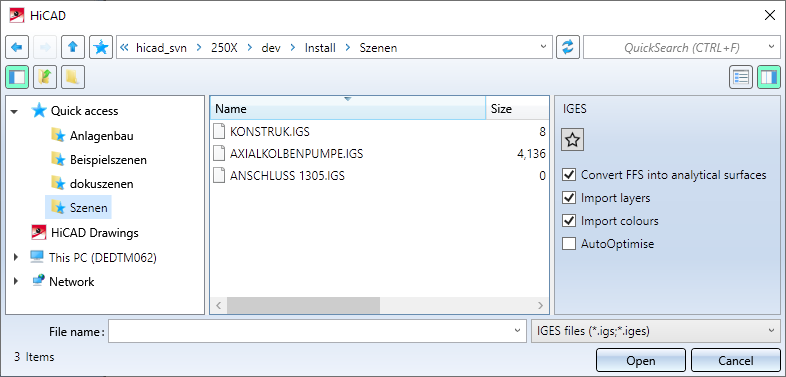
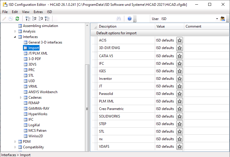
Settings made in the dialogue window for an interface format can be saved as favourites. To do this, click on the  symbol in the dialogue window. You can find more information on favourites management in the in the Manage Favourites topic of the HiCAD Basics Help. You can specify which favourite is used as the default in the import dialogue in the Configuration Editor at Interfaces > Import.
To preset a favourite for a file format, just click on the symbol and choose the desired favourite.
![]() Please also note:
Please also note:
- When starting the import dialogue, please note that the last selected settings for the respective file format are used as default. If you have not made any changes to the settings of the favourite defined in the Configuration Editor, the favourite settings will be used.
- Only 3-D elements will be read, i.e. no feature, no product data and no 2-D data.
- The following conditions need to be fulfilled, as HiCAD has high accuracy standards:
- All parts should have the same tolerance. Field tolerances will not be supported.
- The 3-D models you want to import should have a tolerance of 1/1000. Deviations by factor 10 can be tolerated if the test (see below) has been successful.
- Part names should have a maximum length of 32 characters.
- Free-form surfaces must not include self-intersections within the surface.
- If there are problems after reading the file, we recommend to perform a data structure check.
- The import can also be done by Drag & Drop from the Explorer, in which case the import dialogue is also displayed. This dialogue is preset with the file to be imported and the corresponding options for the file format are displayed. This does not apply to the import of 3-D DXF/DWG.

3-D import into the current model drawing
Drawing > Insert Part > Exp. > 3-D Import
With this function you import files of the above mentioned formats into the current model drawing. The parts of the file - in case of several parts as an assembly - are inserted into the current model drawing with the name of the selected file.
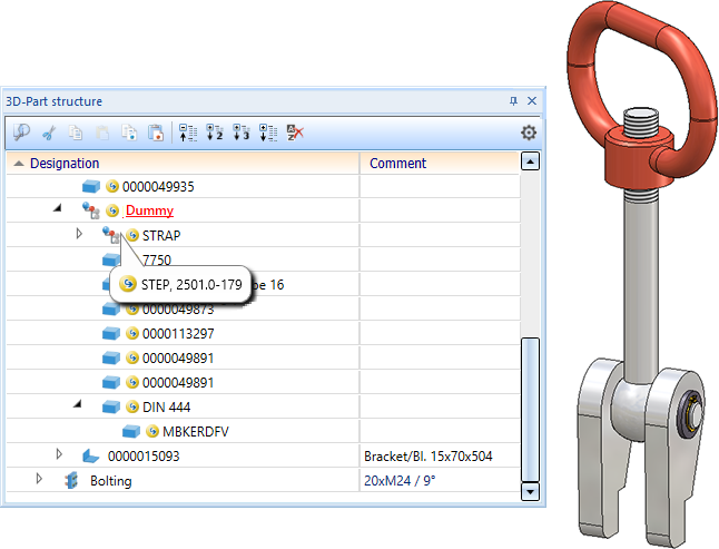
Imported parts are marked with the  symbol in the ICN. If you move the cursor over the symbol, you will receive further information on the corresponding part, e.g. the imported file format and the HiCAD version with which the part was imported.
Parts / assemblies marked with the symbol can be updated with the function Update import, via 3-D interface  or replaced by other imported files.
If there are several parts/assemblies on the top level of the part structure during the import, an assembly will be created with the name of the import file to which these parts are subordinated. This means that each import on the top level consists of only one part or assembly. Only such imports can be updated when the import file is changed.
3-D Export
Export model drawings
Drawing > Save/Print > Save as > 3-D formats (STEP, IFC, 3D PDF ...) 
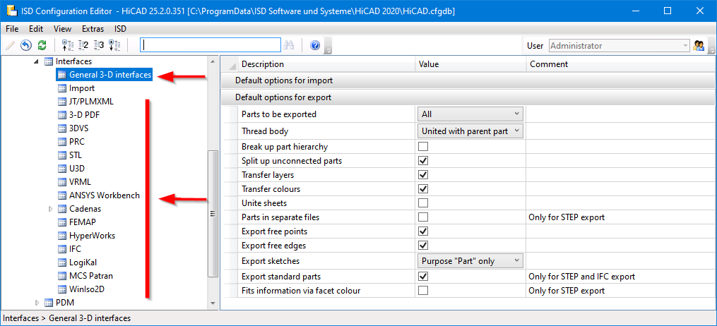
With this function you can export the model drawing to the formats listed above. After calling the function, the corresponding export dialogue is displayed. At the top right of the dialogue window you can specify whether All parts (i.e. the entire model drawing) or a defined Selection list (i.e. a selection of marked parts) are to be exported.
Select the desired file type. The corresponding export parameters are then displayed in the dialogue window.
The default settings for the parameters in the dialogue window are defined via the settings for Interfaces in the Configuration Editor.
![]() Further notes on export:
Further notes on export:
- Alternatively, you can also access the functions via the ISD button
 .
. - When saving via 3-D formats (STEP, IFC, 3D PDF...), HiCAD remembers the last saved file format (if it is a CADFix format) and offers this as default setting for the next export. Furthermore, by clicking on the
 symbol, the current settings can be loaded from the configuration management.
 - Use interface lists if you want to convert several files automatically.
- When writing CATIA V5 files, a file with the extension CAT.PRODUCT is created for model drawing and a file with the extension CAT.PART is created for each part of the model drawing . If you want to transfer the export file, you must ensure that you transfer all the associated files.
Recommendation: Create a separate folder for the export. CATIA import is supported from V4 to 4.2.x and V5 to R23. - When writing Creo Parametric files, files with the file name extension .g are created for model drawing and for the individual parts of the model drawing . If you want to transfer the export file, you have to make sure that you really transfer all the corresponding .g files.
Recommendation: Create a separate folder for the export. Creo Parametric import is supported up to Wildfire 5 (included in PTC Wildfire/CREO Version 2).
Export view
RMB > 3-D Export (STEP, 3D PDF...) by views
If you only want to export the active view, use the corresponding function of the context menu for views.
Export by views is possible for the following formats:
- 3D PDF
- Universal 3D
- Product Representation Compact
- 3D ViewStation
- STEP
- 3-D DXF/DWG (DXF, DWG)
- IGES
- VDAFS
- CATIA V5
- ACIS
- Parasolid
- Creo Parametric
- JT
- PLM XML
![]() Please note:
Please note:
- Only parts that are visible in the view are exported.
- The export is also possible for sectional views.
- For exploded views only the export by views to 3D PDF, Universal 3D, Product Representation Compact and 3DViewStation is possible. During normal export, the parts are exported in their original position.
