IFC

IFC import
Drawing > New/Open > Open  > 3-D Import
IFC files are opened in HiCAD by calling the function 3-D Import and then selecting the corresponding *.ifc or ifczip file.
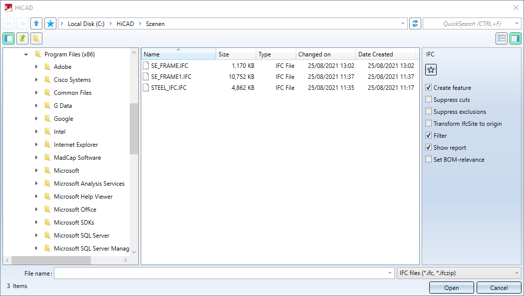
On the right side of the dialogue window, you can set Options for import by activating/deactivating the checkboxes.
Click Open to close the dialogue window and start the import of the currently selected objects. If you click Cancel, the dialogue window is closed and the import is cancelled.
Please note:
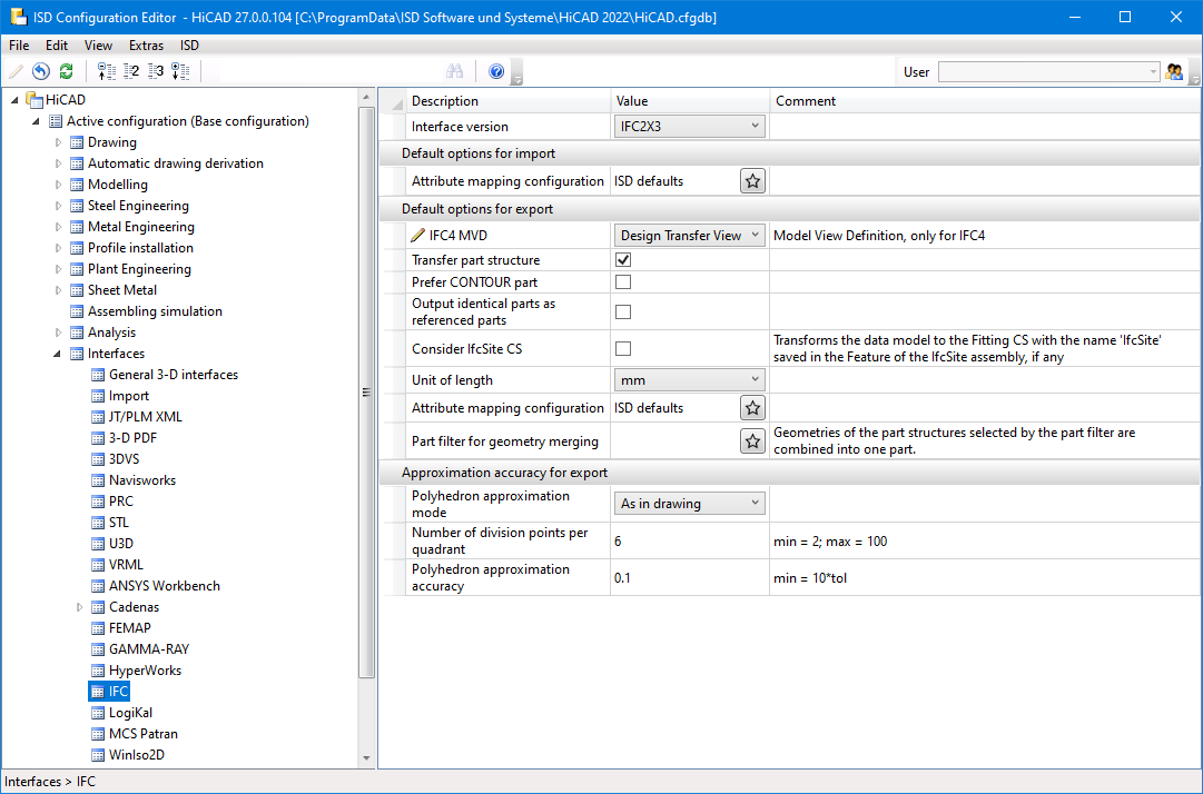
You define which IFC attributes are assigned to which HiCAD attributes in the Configuration Editor at Interfaces > IFC via the parameter Attribute mapping configuration. This is available for both import and export.
![]() Please note:
Please note:
-
The default settings in the dialogue window as well as other parameters can be defined in the Configuration Editor at Interfaces > IFC.
-
When importing beams and profiles via IFC, the default representation (exact or simplified) defined in the Steel Engineering Settings
 function is now taken into account.
Options for import
Settings made in the dialogue window for an interface format can be saved as favourites. To do this, click on the  symbol in the dialogue window. You can find more information on favourites management in the in the Manage Favourites topic of the HiCAD Basics Help. You can specify which favourite is used as the default in the import dialogue in the Configuration Editor at Interfaces > Import.
Create feature
Clear this checkbox if you do not want feature data to be saved in HiCAD after import. During IFC import, parts are generated using feature calculation. If the checkbox is inactive, this feature data is discarded. This can be useful for complex designs, since feature data can impair performance.
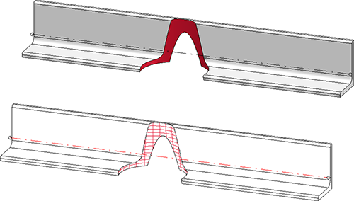
Suppress cuts / exclusions
You can suppress processings when importing IFC files. This is possible for
- Cuts (trimmings, mitre cuts, notches etc.) and
- Exclusions (bores, subtractions etc.).
 Please note that the suppression only applies to explicit mechanical processings and not to faceted parts. For example, the processing shown in the figure is always imported.
Filters
If the Filter option is active, the IFC import filter dialogue window is called after clicking Open. Here you can filter the objects for the import.
Transfer IfcSite to origin
If the checkbox is active, IfcSite (topmost element, including sub-elements) is transformed to the origin. The original coordinate system is saved as an installation coordinate system called IfcSite in the feature of the IfcSite assembly.
Show report
If the Show report checkbox is active, a report with errors, warnings and further information is displayed after the import.
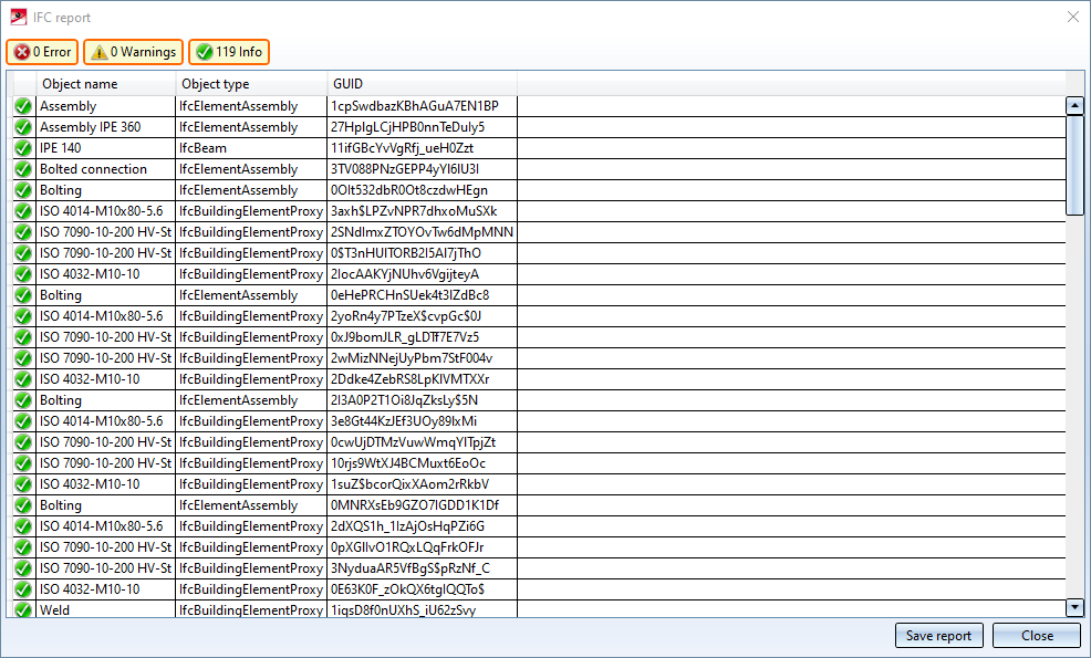
By clicking on an entry in the report, further information about the object is displayed. By clicking on the Create report button, the report can be saved as a CSV file.
Set BOM-relevance
Activate this checkbox to assign the attribute BOM-relevant to the imported parts.
Setting filters
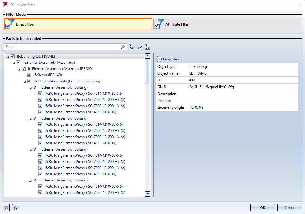
If the Filter option is active, the IFC import filter dialogue window is displayed after clicking Open. Here you can restrict the parts to be imported by specifying direct filters or attribute filters.
Please note:
Sie können entweder Direktfilter oder Attributfilter verwenden. Eine Kombination von Direkt- und Attributfiltern ist nicht möglich.
Wird der Filtermodus gewechselt, dann gehen die aktuell eingestellten Filter verloren. In diesem Fall wird die folgende Meldung angezeigt: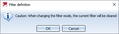
Direct filters
In this mode, you can select objects to be excluded from import by activating the corresponding checkboxes in the tree structure. HiCAD also supports multiple selection with the CTRL and SHIFT keys.
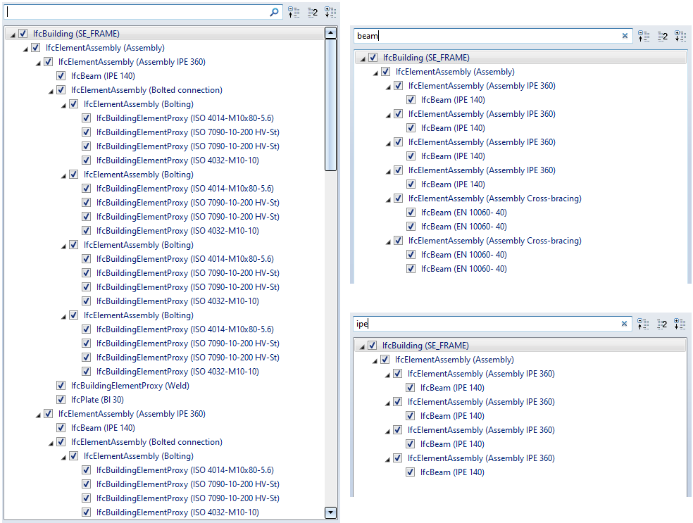
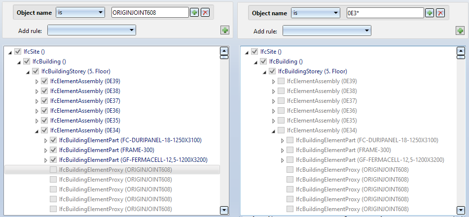
In addition, you can enter a string at the top of the dialogue window, according to which the import is to be filtered. This can be any sub-string of the IFC name or IFC type. Example, for example beam. The tree structure is adjusted immediately. If you then enter another sub-string, the tree structure is filtered further.
In the following example, the partial string beam was specified first and then ipe.
Clicking on  in the input field removes the filter again.
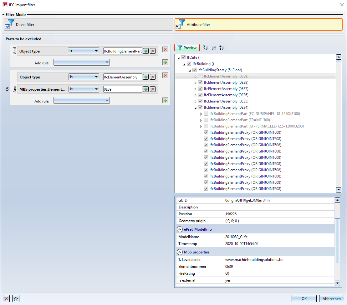
Attribute filters
Instead of direct filters, attribute filters can also be used. Here you can filter the structure by inserting corresponding rules according to various IFC properties and property sets. These property sets depend on the source system and the respective file. Several filter criteria can be combined with AND or OR.

No rules have been preset by the ISD, i.e. no parts will be excluded from the import.
The definition and combination of rules is carried out analogously to the Part filter function. To add a rule, select the desired filter criterion in the Add rule selection box, e.g. Object type, and then the condition that must be fulfilled, e.g.:
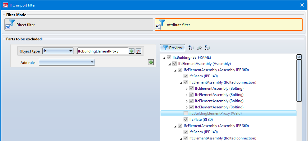
In the example shown, all parts with the object type IfcBuildingElementProxyy are excluded from the import.
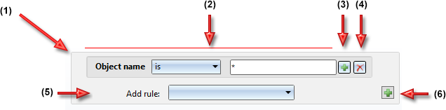
Attribute filters can consist of one or more rule blocks, each rule block being identified by a grey rounded rectangle (1). A rule block consists of one or more rules, which can be linked by AND or OR. Each rule (2) contains the attribute to be filtered by and the condition it must fulfill. This condition consists of an operator and a string, where the allowed operators here are is and is not. The string can contain the wildcard characters *, ? and \.
|
|
(1) |
|
Rule block |
|
(2) |
|
Rule V |
|
|
(3) |
|
Add OR rule to current rule block |
|
|
(4) |
|
Remove rule / rule block |
|
|
(5) |
|
Add AND rule to current rule block As rules you can choose the following Properties:
In addition, you can also use Property Sets (depending on the original system) for filters. |
|
|
(6) |
|
Add new OR rule block If you click on the symbol holding down the CTRL key, the rule block is copied. If several rule blocks exist, you can delete control blocks with a click on the |


 symbol.
 |
Wildcard |
Function |
Example |
|---|---|---|
| * |
Placeholder for any number of characters |
All (*), starts with Prof (Prof*), contains Prof (*Prof*), ends with Prof (*Prof) |
|
? |
Placeholder for exactly one character |
Profile? or Prof???? |
|
\ |
As masking characters |
Search for * in the text (\*), Search for \ (\\) |
Some examples of attribute filters:
The following scenarios can also be covered by the attribute filters:
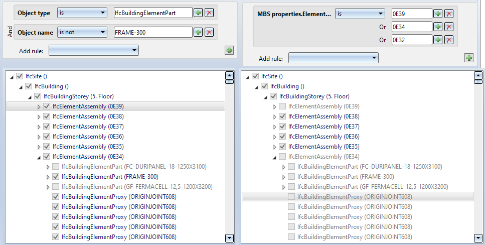
- Exclude all assemblies with the name xxx including the sub-parts as well as all parts with a certain criterion from the remaining assemblies
- Importing all assemblies with the name xxx except parts with certain criteria
Please note:
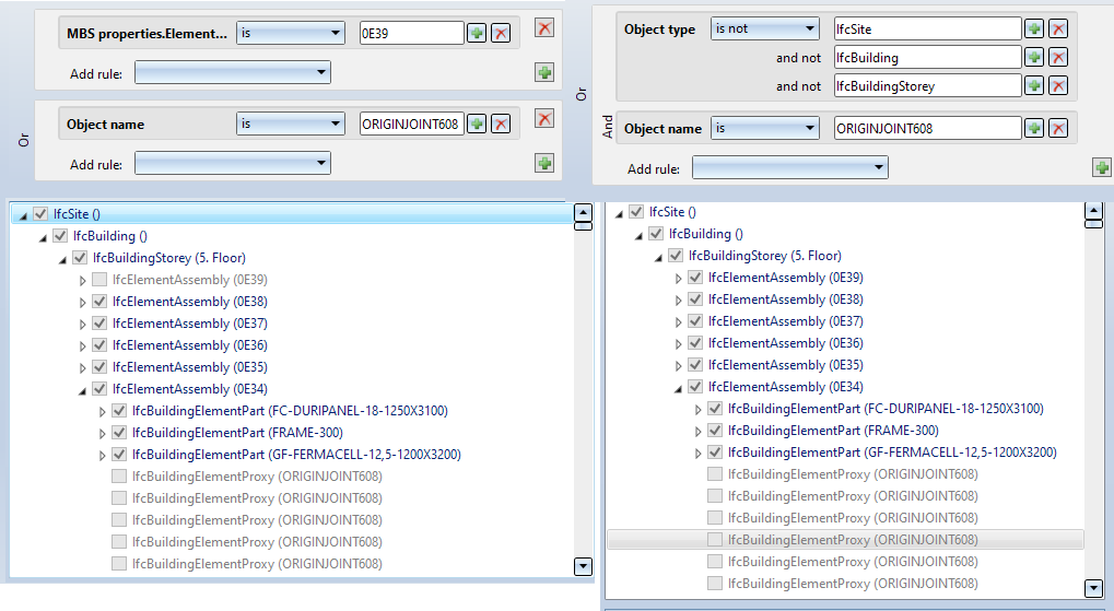
The parts to which the filter applies will be excluded from import including their sub-parts. This is true without exceptions. Therefore, the "is not" condition is only useful in special circumstances.
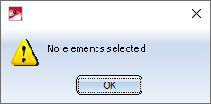
An example: In the example shown, the elements should be excluded whose object type is not ifcElementAssembly. The filtering is started at the top assembly (IfcSite). This fulfills the specified filter criterion. As a result, all sub-parts are also excluded. So the selection is empty.
If the current filter settings result in all parts being excluded, then a corresponding message is displayed.
The Preview can be switched on and off. If it is switched on, the filter is applied immediately after each change to the filter rules, that is, the objects in the tree structure that fulfil the filter conditions are activated immediately on the right of the dialog box.
If you want to empty the filters, that is, reset them to the ISD-side default settings, click on Clear filter  in the bottom left of the dialogue window. By clicking on
  you also start the Favourites Management here. Attribute filters can thus be saved for reuse.
Click Open to close the dialogue window and start the import of the currently selected objects. If you click on Cancel, the dialogue window is closed and the import is cancelled.
IFC export
Drawing > Save/Print > Save as > 3-D Formats (STEP, IFC, 3D PDF ...) 
You use this function to export HiCAD model drawings into the IFC format or as a packed IFC file into the IFCZIP format. To do this, select the required file type.
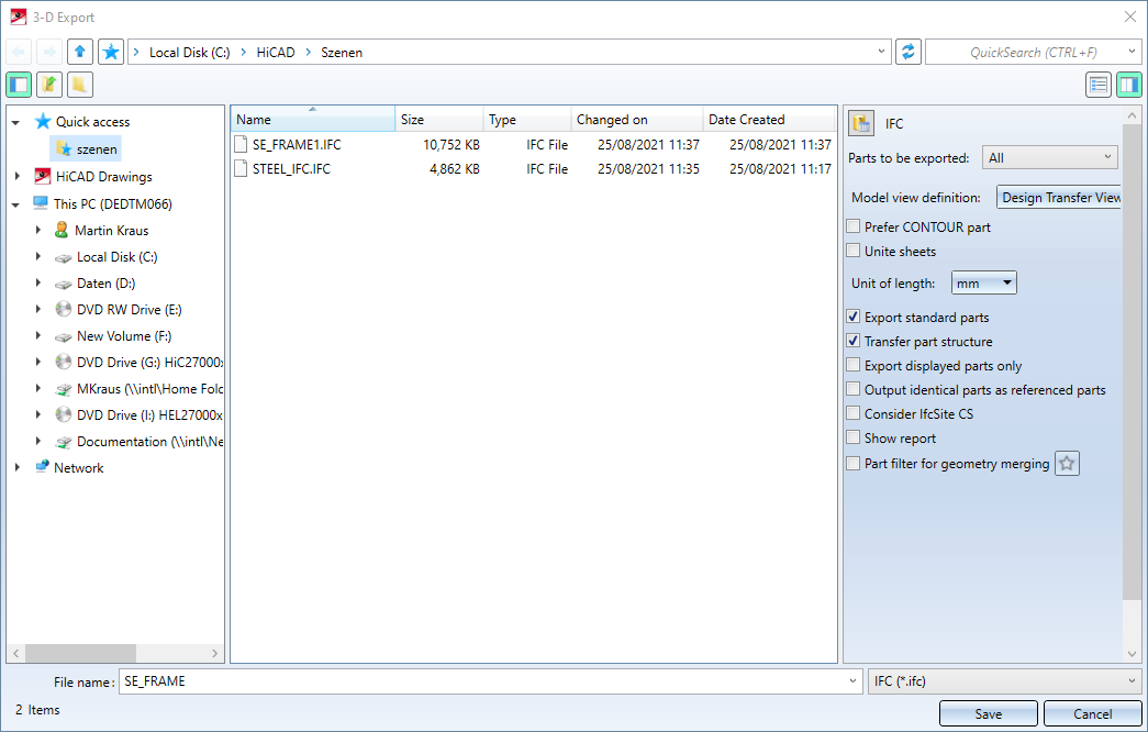
On the right hand side of the dialogue window the following options are available:
- Parts to be exported
Select whether All parts (entire construction) or only a Selection list (marked parts) should be saved. - Prefer CONTOUR part
If you activate this checkbox, the system checks whether a CONTOUR representation is available during export and then exports it. If none is available, the EXACT/SIMPLE representation is exported, which is also written out if the check mark is not set. - Unite sheets
Check this box if you want to combine all the lower parts (including tabs and bending zones) of a sheet with the higher-level bend plate into one part during export. - Unit of length
This option allows you to specify whether the length information in the IFC file is to be output in millimeters (mm), meters (m), or inches. - Model View Definition
This setting is only visible if you have selected IFC as the interface version IFC4 in the Configuration Editor at Interfaces > IFC. In this case, you can select here which definition is to be used for the export as IFC data model.
- Design Transfer View
This is the default setting for the IFC export. In contrast to the Reference View, where the exported model should not be changed, it is possible to make changes to the exported model when exporting via IFC4 Design Transfer View.
- Reference View
This setting assumes that the exported model is not to be changed. This makes sense if the exported model is only to be used for pure coordination purposes, e.g. for visualisation, collision detection, quantity takeoff, etc., and therefore no absolutely exact geometry is required. The geometry is represented "simplified" here, i.e. simple geometry with extrusions only, complex geometry as a tessellated polygon mesh. With this definition, there are also fewer compatibility problems in the IFC management programs than with the IFC 4 Design Transfer View.
- Export standard parts
This can be used to define whether standard parts (screws, roller bearings, springs, etc.) are to be output with the IFC export. - Transfer part structure
If this option is active, the substructure is transferred with its actual hierarchy. If it is inactive, all parts are on the same level - similar to a BOM. - Export displayed parts only
If this checkbox is activated, you can only include the currently displayed parts in the export instead of an IFC export of all parts of the construction. - Output identical parts as referenced parts
It is worth selecting this option when exporting designs with many identical parts. Identical parts are then grouped together as references, which reduces the amount of data and improves performance. - Consider IfcSite CS
If the checkbox is active, the model is transformed into the installation coordinate system called IfcSite, if available, stored in the feature of the IfcSite assembly (topmost BG). - Show report
If this checkbox is active, a report is displayed - as with the import - ,with any errors, warnings and other information that may have occurred. By clicking the Report Output button, the report can be saved as a CSV file. - Part filter for geometry merging
Here you can specify that assemblies / main parts and their sub-parts are combined into one part during export.
To use part filters, activate the checkbox Part filter for geometry merging and then - after clicking the symbol - the part type. All parts filters defined with the Search via toolbar (Part filter)  function are supported. The following part filters are already predefined:
| Industry | Part type | |
|---|---|---|
|
General
|
Referenced part |
|
|
Sketch |
|
|
|
Solid |
|
|
|
Plant Engineering
|
Straight pipe |
|
|
Elbow |
|
|
|
Pipeline |
|
|
|
Sheet Metal |
Sheet |
|
|
Mechanical Engineering |
Standard part |
|
|
Steel Engineering
|
Facade assembly |
|
|
Steel Engineering assembly |
|
|
|
General part |
|
|
|
Facade part |
|
|
|
Steel Engineering part |
|
|
Example:
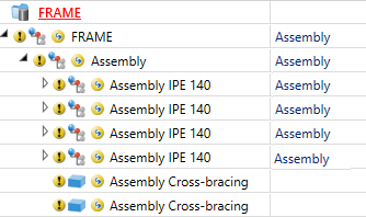
A Cross-bracing (2602) has been installed between four beams. Cross-bracing was chosen as usage for the beams in the cross-bracing dialogue.
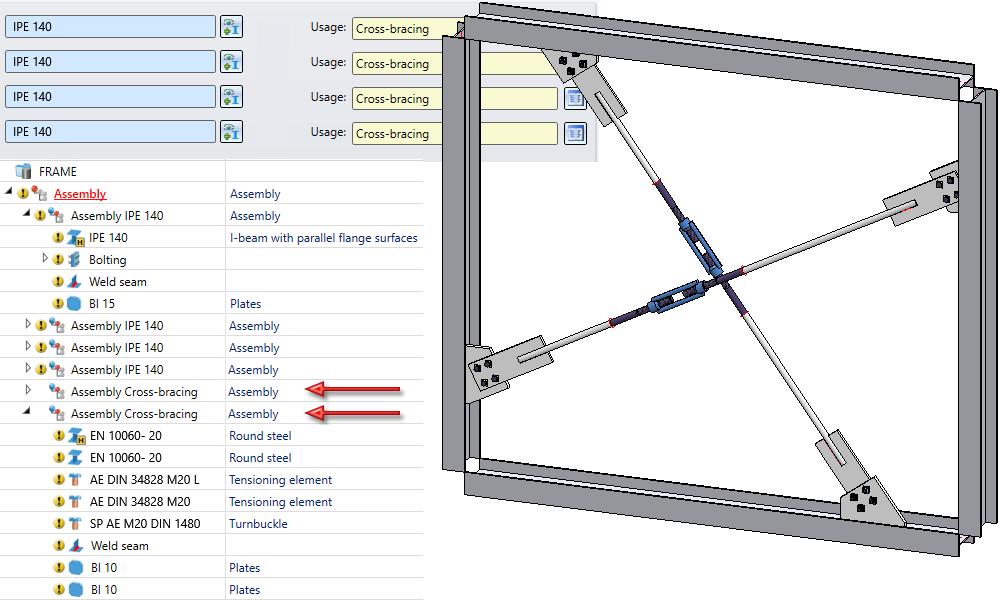
The two marked assemblies then have the usage Cross-bracing. If the model drawing is exported as an IFC file using the part filter Steel Engineering > Steel Engineering assembly > Cross-bracing, the parts of the assemblies will be combined into one part each.
![]() Please note:
Please note:
- The default settings, which export options should be activated or excluded when the dialogue is called, can be set in the Configuration Editor at Interfaces > IFC. The parameters set there can be loaded in the dialogue window by clicking on the
 symbol.
 - When inserting 3-D CAD formats (STEP, Iges, ...) into HiCAD, they are automatically opened in a new drawing file created for this purpose.
- When importing IFC files, the parts list relevance of parts and assemblies is automatically removed.
- If standard beams or profiles are contained in an IFC file, they only become corresponding standard parts in HiCAD during import if the designation of the beams or profiles in the IFC file corresponds to the designation in HiCAD. Using the Catalogue Editor (CATEditor), you can control how standard parts are transferred from IFC to HiCAD in the mapping table at Catalogues > Factory standards > IFC interfaces > IFC Mapping ISD.
- You can set the IFC format version (IFC2x3 or IFC4) in the Configuration Editor at Interfaces > IFC >Interface version.
- HiCAD supports the Coordination View 2.0 subschema. You can find more information on the website of buildingSMART International.
- Special IfcProduct-based objects (e.g. electrical components) are not interpreted separately. This means that only connected geometries are processed (including properties such as materials/colours/PropertySets etc. and parameterisations, e.g. for beams and profiles).
