Step 8: Plan staggered bores
Let us assume that the bores are to be inserted with a horizontal displacement of 15 mm from the intersection point.
- Take a look at the Feature log entry for the Asbestos cement panel. The bore have been inserted, via absolute coordinates, into the origin of the processing coordinate system, which in turn has been placed into the intersection point of the connections. This means that the bores can be moved by changing the relevant coordinates.
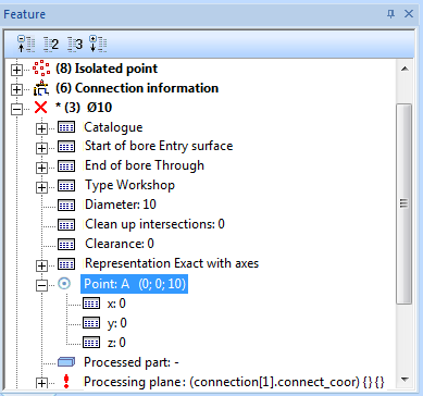
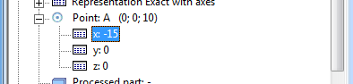
- Change the first bore in such a way that the point does no longer lie in the coordinates
0 0 0, but in-15 0 0.
- Proceed likewise to change the second bore, so that it lies in the coordinates
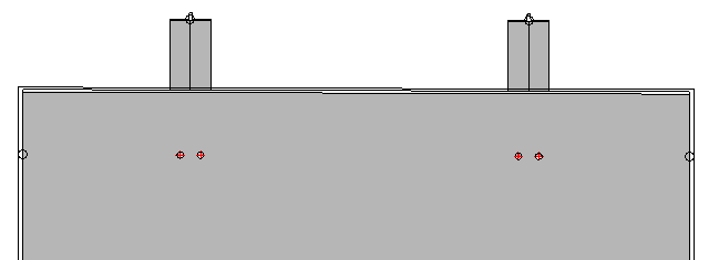
15 0 0. As we still know from Step 7, the two bores have different Processing planes and Conditions. However, we can ignore this here, because the following calling of the Repeat connection processing function will set these values anew. - Choose Civil Engineering functions > Element installation > Repeat connection processing. Select both bores beneath Feature, Choose a Total quantity of 2 and select the Connection geometry again.
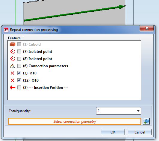
- Both processings will be copied and the values for the Processing plane and Condition will be set correctly.
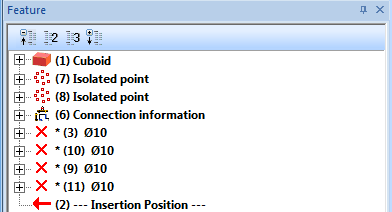
- Save the part and update the element installation and the connection.
Now, two bores to the left and right of the centre of the beams will be created. One problem becomes obvious immediately when one of the sub-structure beams is rotated:
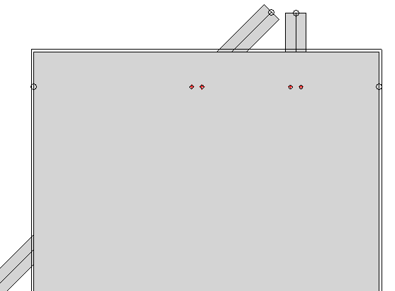
Here it would be desirable if the bores could be rotated as well.
Next step: Use foreign coordinate system

