To be able to create your own variants that a suitable for a use of the Connection function, these must be prepared accordingly.
In addition to the technical information provided in this topic you can also study a concrete example.
Connection information
Both variants that are to be linked (that is, normally the elements of the element installation and the beams/profiles of the sub-structure) require a Feature log entry called Connection parameters. You create this entry by selecting Civil Engineering functions > Element installation > Connection parameters  .
.
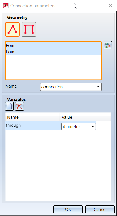
The displayed dialogue window will then query the following information:
- Geometry -Specify the points that form a
 composite edge or a
  polygonal surface used to determine the intersection points of the connected parts.
 - Name - A name for this connection parameter - it will be used to set the connection parameter as a part variable in the current part.
- Variables - A list of variables that is to be additionally set for the connected part. These in turn consist of:
- Name - The name that the variable of the connected part is to obtain.
- Value - The value that the variable of the connected part is to obtain. Typically, the value is defined via a value of the connected part; it can, however, also be a fixed value.

How to create a connection
If two parts with specified Connection parameters are linked to each other with the Connection function, a number of actions will be carried out. These will be applied to both parts.
- The intersections of both parts will be determined. For this purpose the composite edges defined in the Connection parameters of both parts will be used. These will be projected onto the Processing planes on which the connection is based. If the geometries in both connection parameters consist of composite edges, the intersection consists of one or more intersection points. If one connection parameter contains an composite edge and the other contains a polygonal surface, the intersection consists of one or more composite edges.
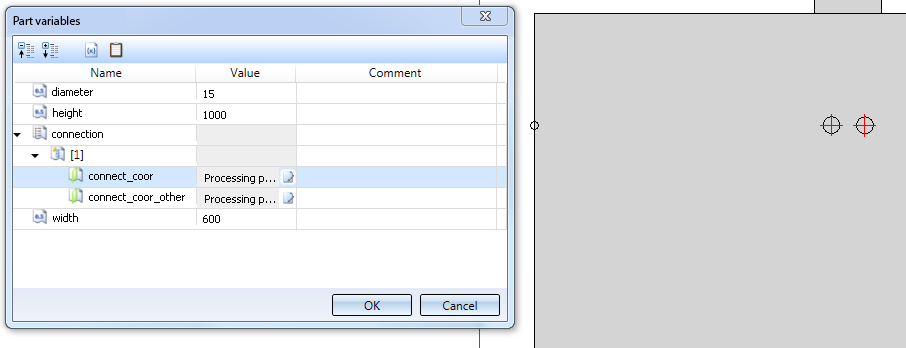
- For the active part, the intersection points will be saved as part variables. A list variable named according to the Name in the Connection parameters dialogue will be used for this.
- For an intersection defined by intersection points, this list variable contains one structure variable per intersection, which contains the following entries:
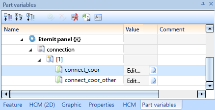
- connect_coor contains a processing plane. The origin of this processing plane id the current intersection point, projected onto the (sketch) plane on which the active plane is based. The X-axis of the coordninate system points in the direction of the connecting edge of the current part.
- connect_coor_other also contains a processing plane. Its origin also lies in the current intersection point. Here, the X-axis of the coordinate system corresponds to the connecting edge of the other part.
- If Variables have been defined in the Connection parameters of the other part, its values will also be taken over as entries into the structure variable.
- In the case of an intersection of composite edges, this list variable contains one structure variable per composite edge. This structure variable contains the connect_path entry which contains the X, Y and Z coordinates of the composite edge points. This variable is only created on the part with the polygonal surface. No variables are then created on the part with the composite edge.

- If Variables are defined in the connection parameters of the other part, their values are also transferred as entries to the structure variable.
The variable created in this way can be evaluated by means of the additional Connection simulation function.
Recalculate a connection
After applying changes to a part of a Connection, these changes will not automatically affect the connection. This will only happen after a Recalculation of the superordinate assembly.
To do this, select the superordinate assembly, right click in the Feature log (even if the assembly itself does not have a Feature log entry, so that the Feature log is empty!) and choose Recalculation.
Additional functions
To facilitate the development of own variants with connection parameters, two additional functions are available that are particularly helpful for error detection:
Repeat connection processing
The function Civil Engineering functions > Element installation > Repeat connection processing  function repeats processings and sets their parameters to be able to use the parameter connect_coor correctly.
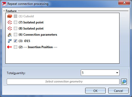
In the Repeat connection processing dialogue window you can choose the processings to be repeated by activating their checkboxes. Please note that at least one processing must be selected here. Otherwise, the error message No processing selected! will be displayed.
The Total quantity field determines how many times the processing is to be repeated. Please note that you do not specify here how often the selected processings are to be repeated, but how many processings are to be there after executing the function. If you choose the value 1, no copies will be created, but only the selected processings will be parameterized.
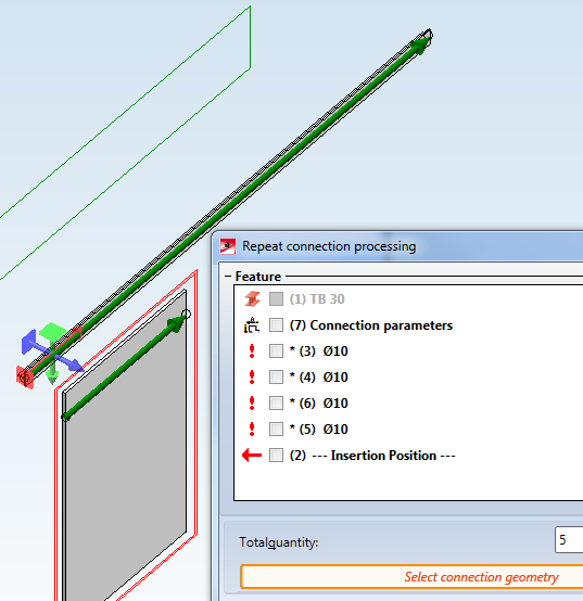
In the Select connection geometry field you need to choose the connection geometry that is stored in the desired Connection parameters. After clicking on the  button, all connection geometries will be highlighted by green arrows in the model drawing. Choose the desired connection geometry with a left-click.
After confirming with OK, the following steps need to be taken:
- Copy the selected processings as many times as necessary to reach the number in the Total quantity field.
- Set the fields Processing plane and Condition for each processing. In this example, let the name of the connection parameters
suspension. The first copy of the processing then obtains the following values:
- Processing plane:
suspension[1].connect_coor - Condition:
length(suspension)>=1
- The second copy obtains the following values:
- Processing plane:
suspension[2].connect_coor - Condition:
length(suspension)>=2 - Proceed likewise for the remaining copies (to understand the meaning of these variables, please read the information given in the How to create a connection paragraph further up).
Connection simulation
The function Civil Engineering functions > Element installation > Connection simulation  performs the same steps on a variant as would be the case for a connection, but with the following differences:
- The connection will only be performed on one of the two parts to be connected.
- This part must exist as a "normal" part and must not be installed a sub-structure or an element installation.
- The changes are not made as part of a Feature step, but are directly applied in the part variables.
In this way you can check exactly which intersection points and which resulting processing planes would be considered for a connection.
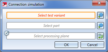
First, identify the variant to be tested. Make sure that you choose the correct part in the structure (e.g. a superordinate assembly), since HiCAD cannot determine it on its own. The part variables will then be changed on this part.
Identify the other component of the connection as its second part. This can either be a sub-structure or an element installation, but also another variant. No changes will be applied to it.
The Select processing plane option behaves the same way as in the Connection dialogue window.
After a click on the OK button, the variables will be set on the test variant, in the same way as with a "real" connection.
![]() Important:
Important:
When you perform this step, value inputs for the part variables of the selected part will be generated immediately. You need to delete them before saving the part to the catalogue, since otherwise a later connection would fail.
Show connection geometries
After choosing Civil Engineering functions > Element installations > Connection geometries  HiCAD will prompt you to identify a part. If this part contains connection information, the composite edges defined there will be highlighted red in the model drawing:
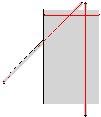
You can then select further parts to have their composite edges displayed. If you select an assembly, the composite edges of all parts contained therein will be displayed.
Press the middle mouse button to end the function.
