Step 5: Prepare sub-structure for connections
For the sub-structure, too, a connection information feature needs to be entered. However, no processings are planned here for the time being. Here, too, make sure that you process the part in the assembly Variants, and not the parts created via the sub-structure.
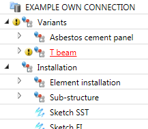
- Select the assembly T-beam.
- Choose Civil Engineering functions > Element installation > Connection parameters.
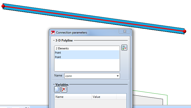
- Snap the first point, namely, the mid point of the upper edge on the left border.
- Place the second pint at the other end of the beam with the point option R and by specifying the coordinates
length 0 0. The relative specification with the variable length ensures that the point will still be located at the other end of the beam in case of its length change. - Enter the Name:
conn(here you may also useconn, as you did for the element installation. There is no technical reason to use a different name here ). Click OK to close the dialogue window.
- Save the part. Proceed as described in the last two paragraphs of Step 1: Create variant for element installation. You can ignore the message stating that the catalogue entry cannot be edited; answer the question, whether you want to overwrite the file with Yes.
Next step: Update sub-structure, element installation and connection

