Installation elements can also be defined variably. For this purpose, the i_nr variable can be used. A number of corners n will be assigned to this variable. This allows an installing of this element on sketch areas with 3 to up to n corners.
In addition, the variables of the 4th, 5th and nth corner point must contain a query for the number of corners of the sketch area, namely, as follows:
|
Corner point |
Formula |
Effect |
|---|---|---|
|
4th corner point |
i_nr>3?x3:x0 i_nry>3?y3:y0 |
If the selected sketch area has 3 corners, the 4th corner point of the installation element will be placed into the 1st corner point, i.e. a triangle will be created. |
|
5th corner point |
i_nr>4?x4:x0 i_nr>4?y4:y0 |
If the selected sketch area has 4 corners, the 5th corner point of the installation element will be places in the 1st corner point, i.e. a rectangle will be created. |
|
.... |
..... |
|
|
nth corner point |
i_nr>n-1?xn-1:x0 i_nr>n-1?yn-1:y0 |
If the selected sketch area has n-1 corners, the "nth corner point -1" will be placed into the 1st corner point, i.e. a "n-1-gon" will be created. |
 If you want the installation to be possible on rectangular sketch areas, you need to additionally use the variants i_l (Length) and i_h (Height)!
The syntax used for the formulas is a conditional expression. This has the form condition?value1:value2. If the condition is true, value1 will be returned; otherwise value2 will be returned.
i_nr>3?i_x3:i_x0 therefore means: If i_nr>3 is true (i.e. there are more than three / at least four corners), then i_x3 will be returned (i.e. the X-coordinate of the 4th point). Otherwise i_x0 will be returned (i.e. the X-coordinate of the first point).
Since this is done here analogously for the Y-coordinate, the 4th corner is placed at the coordinates of the 4th point in the case of i_nr>3 - and otherwise at the coordinates of the first point, causing the corner to "disappear".
An example:
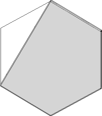
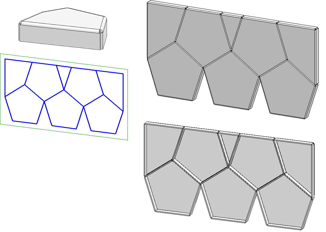
Let us assume that you want to create a pentagonal sheet with flanges as an installation element. This sheet is to be adjusted to - and subsequently installed on - triangular and rectangular areas.
The basic procedure is quite similar to that for the example with the triangular sheet. However, the variable i_nr will be used here.
- Step 1 and 2: Create and parameterize the installation element
- Step 3: Define a Fitting CS
- Step 4: Save installation element to catalogue

Step 1 and 2: Create and parameterize the installation element
- Create a new drawing file and switch to the standard axonometry.
- Choose Sketch > New
 to create a new sketch.
- Choose Sketch > Draw > Line
 to draw two lines as shown below - one parallel to the Y-axis, the other one parallel to the X-axis. You will need these lines as an auxiliary geometry for parameterization, i.e. they virtually symbolize the coordinate system for the corner points of the pentagonal shape that you want to draw.
 - To prevent that these auxiliary lines will be considered for the derivation of the sheet, define them as auxiliary geometry. To do this, choose Sketch > Tools > Sort GE
 > Auxiliary geometry
  and select the two lines. They will then be displayed as dashed lines.
 - Choose Sketch > Draw > Line and draw a rectangle as shown below.
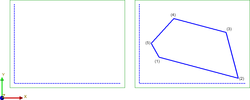
- Now, parameterize the pentagon via its corner points. Choose Sketch > HCM > Smart dimensioning
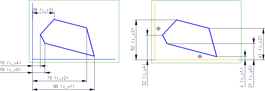
 and specify the distance constraints of the 3 corners to the vertical auxiliary line (HCM scaling = Scale complete sketch). Choose i_x0 and i_x1 to i_x4 as variables.
 - Then, specify the distance constraints to the horizontal auxiliary line (variables i_y0 to i_y4).
- To ensure that the reference to the axes, i.e. to the two lines of the auxiliary geometries, will not be lost, these lines must be fixed. To do this, choose Sketch > HCM > Fix...
 and select the two lines of the auxiliary geometry.
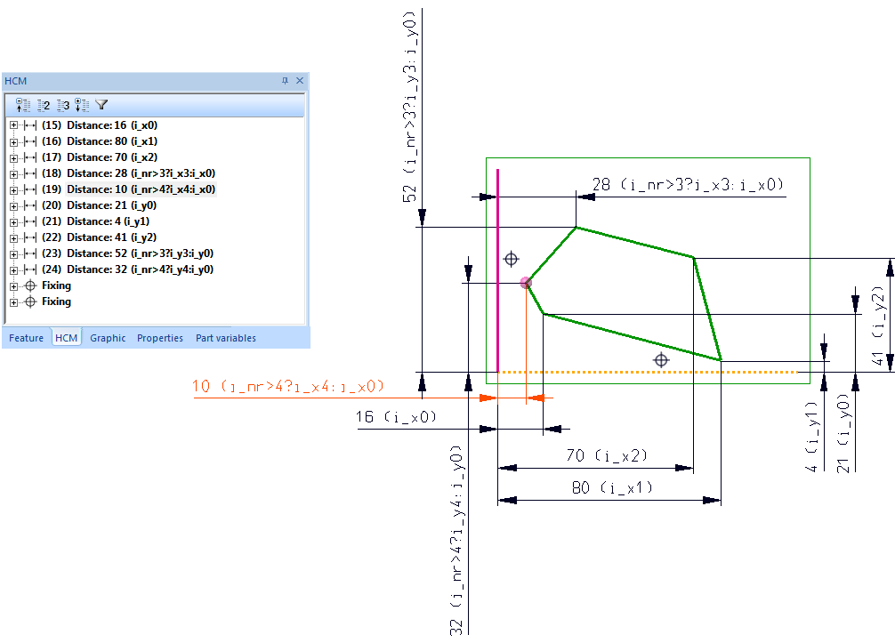
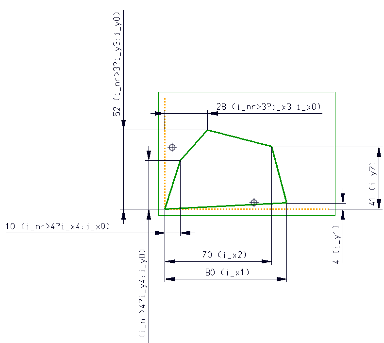
- Since the installation element is to be used variably (.i.e. also suitable for triangular and square sketch areas), the parameter i_nr must be defined and applied to the 4th and 5th corner point, i.e. (i_x3,i_y3) and (i_x4,i_y4).
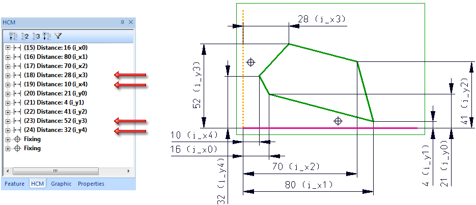
For this to happen, the constraints for the corner points must be changed in the HCM log (double click) in the following way:
|
|
Replace with |
|---|---|
|
i_x3 |
i_nr>3?i_x3:i_x0 |
|
i_y3 |
i_nr>3?i_y3:i_y0 |
|
i_x4 |
i_nr>4?i_x4:i_x0 |
|
i_y4 |
i_nr>4?i_y4:i_y0 |
Since the variable i_nr has not been defined yet, it will be queried. In this example, select the value 5.
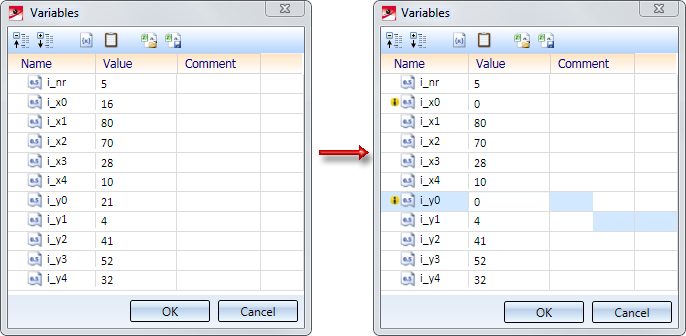
- As the 1st corner point of the installation element is later to lie exactly in the corresponding corner of the sketch area, the variables i_x0 and i_y0 will be set to the value 0. To do this, open the Part variables docking window, change the value of i_x0 and i_y0 to 0, and confirm with OK.
- Now, derive the sheet from the sketch: Choose Sheet Metal > New > FromSkt
 , select the sketch, enter the sheet thickness and close the dialogue window with OK.
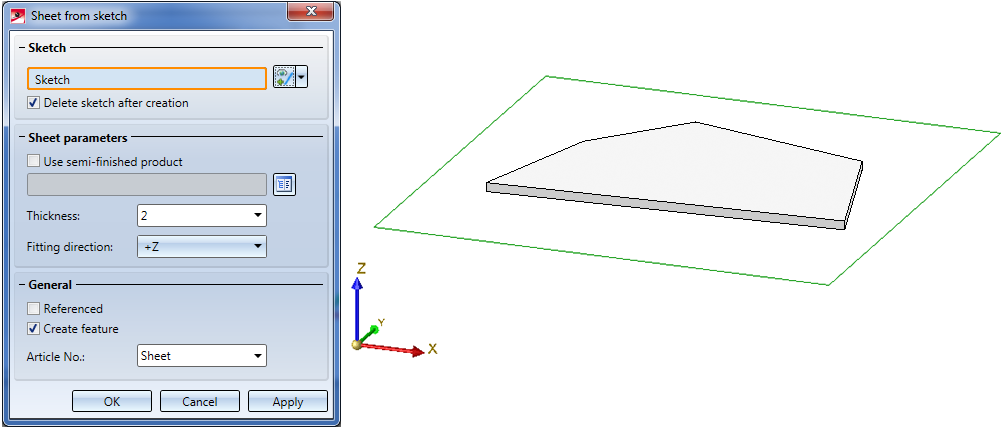
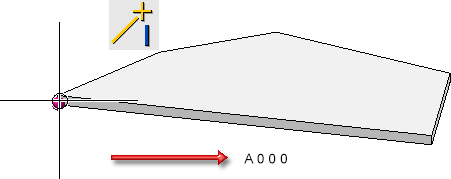
- To ensure that the sheet has the correct position for the later installing, move the sheet to the absolute zero point.
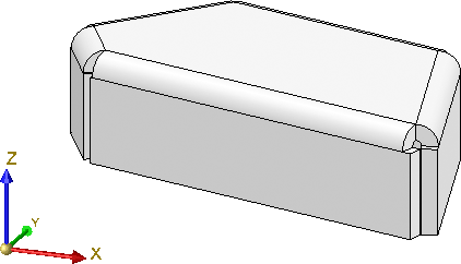
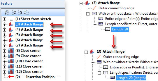
- Now attach the flanges. To do this, choose Sheet Metal > Attach Flange
 .
.
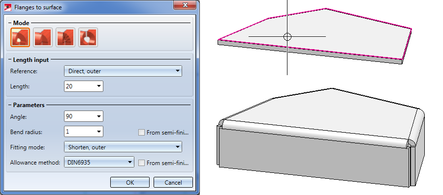
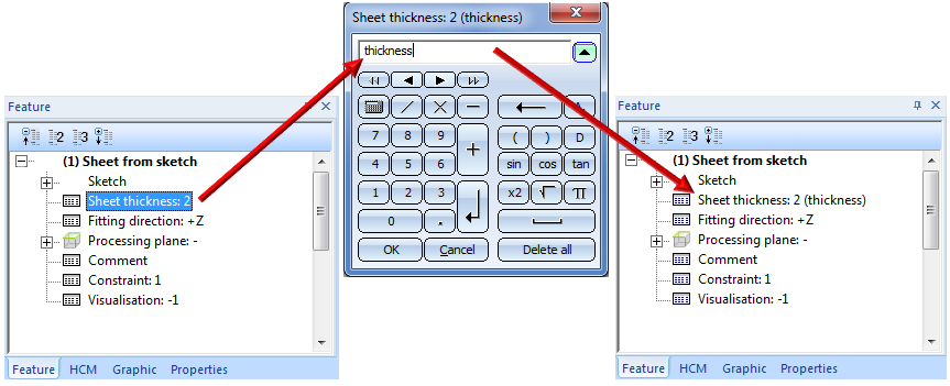
- The sheet thickness must be variable. To achieve a variable sheet thickness, change the corresponding Feature log entry and choose thickness as variable.
- The length of the flange must also be variable. To achieve a variable length, change the corresponding Feature log entries and choose Length as variable.
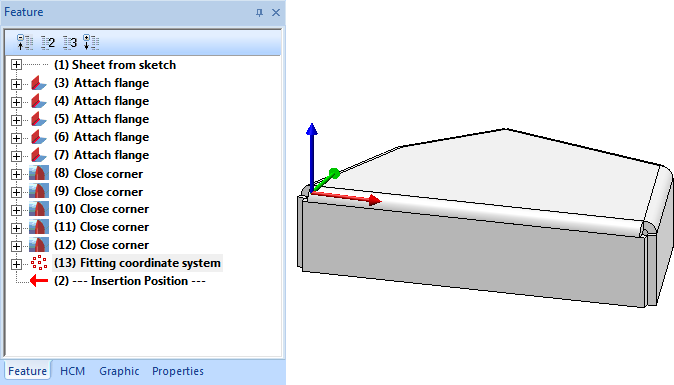
Step 3: Define a Fitting CS
The Fitting CS determines the insertion direction of a part in space. It consists of 3 special points:
- the origin,
- a point on the X-axis
- a point in the (X-/Y-) half plane
If a 3-D part to which a Fitting CS has been assigned is loaded into a new model drawing, the points of the Fitting CS will be placed into the World CS. In this way the insertion direction in space will be determined.
The definition of a Fitting CS is of particular importance if the installation element is an assembly. If this assembly is saved to the Element installation catalogue while no Fitting CS is assigned to it, the Part CS will be used as Fitting CS when the part is inserted. However, this may lead to unwanted results during the installing process.
Please note:
Not all assemblies have automatically a Feature log. For instance, this applies to assemblies that have been created with the Form assembly function, or via New > Assembly. If you assign a Fitting CS to these assemblies, no corresponding Feature log entry will be generated. To achieve this, you must assign a so-called body creation feature to the assembly. To do this, right-click on the Feature window of the assembly and select the Switch feature on function in the context menu. After this, the definition of the Fitting CS will be entered as a Feature here, too.
Continuation of the example:
As already mentioned, the sheet in this example is to be inserted in such a way that the first corner (i_x0, i_y0) lies in the bottom left corner of the selected sketch area. Therefore, a Fitting CS must be defined for the Sheet Metal main part.
Choose Drawing > Others > World CS > Define Fitting CS  and proceed as follows:
(1) New origin of coordinate system is the bottom left corner of the pentagonal sheet (i_xo,i_yo), i.e. Absolute 0 0 0.
(2) Point on X-axis: R (Relative) 200 0 0
(3) Point on y-axis: R (Relative) 0 200 0
The Fitting CS will be entered into the Feature log.
The installation element has been completed and can now be saved to the catalogue.
To be able to directly create a preview image for the catalogue, switch to a non-shaded view beforehand.
Step 4: Save installation element to catalogue
Before saving the variant, change the part name to PENTAGONAL_PLATE.
To save the variant to the catalogue, choose Element installation > Save variant for element installation in the Civil Engineering functions docking window.
- The HiCAD folder KATALOGE will subsequently contain anschließend the files
- PENTAGONAL_PLATE.KRA and
- PENTAGONAL_PLATE.CSV
in the directory Werksnormen\Elementverlegung\Example.
-
The Pentagonal_plate variant is now available in the ISD Example table and can be used for element installation on sketches with 3, 4 and 5 corners, e.g.
.
Please note:
- If you want the installation to be possible on rectangular grids, you need to additionally use the variants i_l (Length) and i_h (Height).
- If the installation element is installed on a grid with more than 5 corners, only the first 5 corners of the installation area will be considered, e.g. like this: