In the dialogue window you can find 3 tabs with setting options:
Further topics:
Please also note the Design Variant e Lasche für SZ-20.

Global settings
Here you can choose the desired semi-fnished product and the parameters for Connection, top, Base point, Connection, left and Connection, right. Furthermore, you can choose here whether standard parts (for fastening) should be installed or not. The ISD default setting is that standard parts are created, i.e. the checkbox is active. If the checkbox is inactive, the standard parts are not listed in the bill of materials.
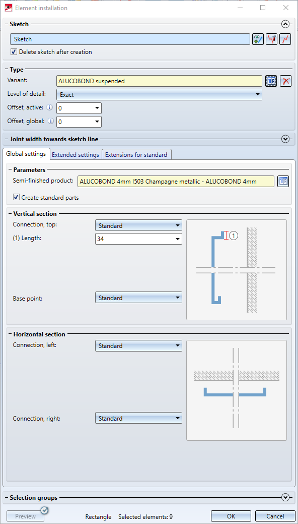
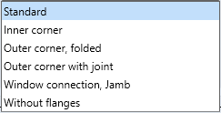
Possible connection options:
|
Vertical section |
|||
|
Top |
|
Base point |
|
|
Horizotal section |
|||
|
Left |
|
Right |
|
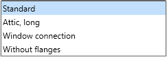
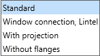

Depending on the chosen connection type, further input fields may be displayed.
If Connection top: Window connection has been selected for the vertical section, the connection can also be installed without flanges. To do this, simply enter the value 0 for Length of folded sheet.
The Attic connection can also be installed without the last flange by entering the value 0 for Length of folded sheet.
If you enter a negative value for Length of folded sheet, the folding will be generated in the other direction ("upwards" or "downwards").
If the option With projection is selected for the connection at the base point, the value Depth determines the length of the first flange. The value Length determines the length of the second flange (top/bottom). If the value 0 is entered here, this flange is not created. If a value < 0 is entered, the edge direction of the flange is reversed. 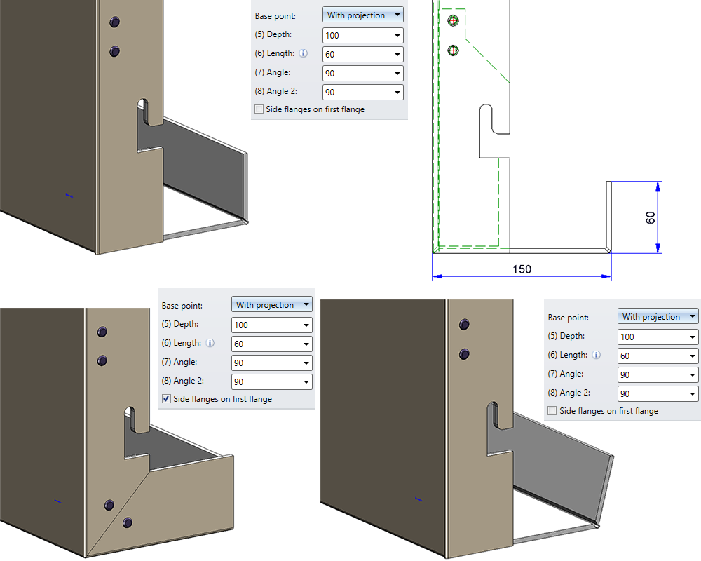
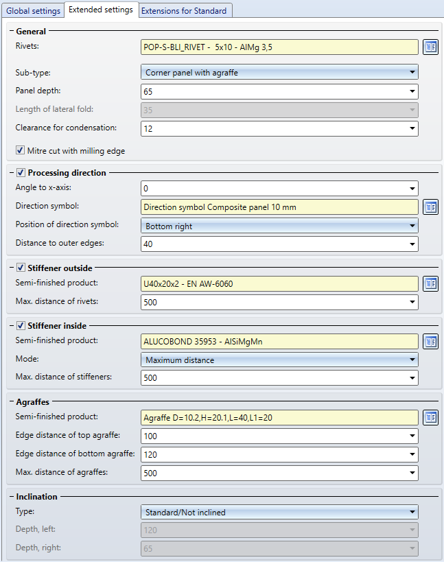
Extended settings
On this tab you can specify further settings such as:
- the tray panel depth,
- the tray panel height, ,
- the sub-type (corner panels with or without agraffe, sheet inserts),
- the direction of the surface textures of sheets,
- settings for stiffeners,
- the semi-finished product for the agraffe (see notes on agraffes further down),
- distances between agraffes,
- the vertical/horizontal inclination (only for the types Standard and Without flanges)
Also, you can specify that the mitre cut is to be shown with a milling edge in the development.
ALUCOBOND suspended- Extended settings
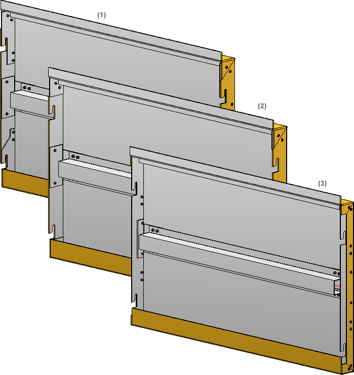
Sub-type: (1) Corner panel with agraffe; (2) Corner panel without agraffe; (3) Sheet insert - with stiffeners at edges and in the middle
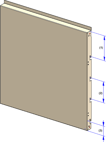
(1) Edge distance of top agraffe; (2) Distance between 2 agraffes; (3) Edge distance of bottom agraffe
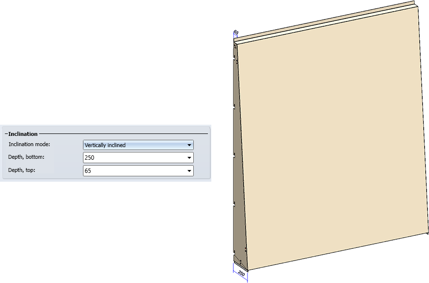
Vertically inclined panel
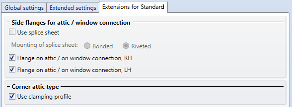
Extensions for standard
On this tab you can find further options for attic connections, similar to the options for the SZ-20 tray panels.
Notes on agraffes
The height and width of the agraffes can be preset in the table Agraffes of the catalogue Factory standards > Bore patterns. In this table two data records have been predefined that you can use as a basis for further sub-types. 
Please note that only agraffes based on the part ISD_AGRAFFE_01-Y.KRA, i.e. agraffes of the Type Y-, are allowed here.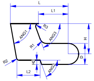
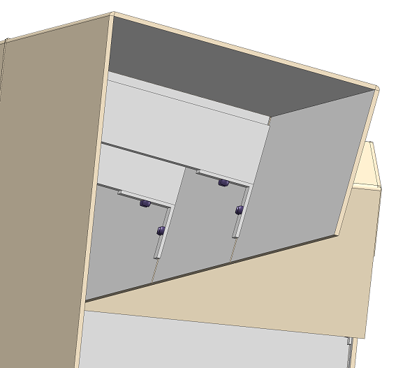
ALUCOBOND suspended, sub-structure
A new sub-structure of the type ALUCOBOND suspended, sub-structure is now available. This part can be mounted to element installations of the type ALUCOBOND, suspended by means of the Connection function; recesses for the suspension will be created automatically in the process.
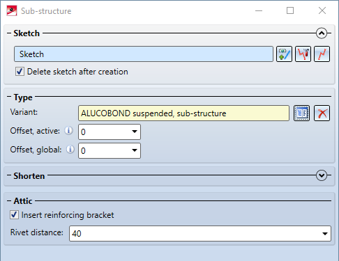
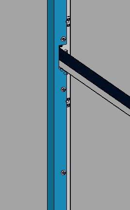
The option Insert reinforcing bracket has an influence on the connection if elements with connection Attic, long are created in the element installation. In this case, the sub-structure and the rear flange of the attic are connected to each other via brackets and riveted: