Subtract, via Translation
3-D Standard > Process with sketch > SubtTra 
You use this function to insert a material subtraction into the active part. The bore is based on a sketch, which penetrates the active 3-D part in all its depth. The part that is created during subtraction is the difference between the active 3-D part and the extruded solid derived from the sketch.
When inserting bores, the multiple selection of parts is also possible. If a part list is active when the function is called, the subtraction will be applied to all parts in the list in one step, provided that they are located in the hole direction.
To create a bore, proceed as follows:
- Activate the
Subtract tab and select Subtract with translation,
through
 as cross-section motion.
 - If the active part is a main part or an assembly, you can use the Include sub-parts and Share feature checkboxes to specify how subordinate parts should be treated during the subtraction.
- Include sub-parts
If this checkbox is active, the subordinate parts located in the hole direction will also be subtracted. - Share feature
If this checkbox is active (default setting) the subordinate parts located in the hole direction will also be subtracted here. In addition, however, the system also checks whether a feature log is assigned to the processed parts. If it is, the feature log of the subtraction will also be assigned to these parts. This means that, in case of a feature recalculation of these parts, the subtraction will also be preserved. If the checkbox is inactive, on the other hand, the subtraction feature will only be assigned to the main part or the assembly that is active when the function is called.
- If you want the subtraction to be created with a draught, enter the angle of inclination. The position of the form-inclination is influenced by the plus/minus sign.
- If you want to
use an existing sketch, click the Select sketch
 button and identify the sketch.
To create a new sketch, click the New sketch button. HiCAD displays the Sketch tab.
Create the desired sketch.
 - Define the other options by activating/deactivating the checkboxes.
- Click the Preview button to display the result.
- Click Apply if you want to apply the bore as displayed in the preview.
Example graphics:

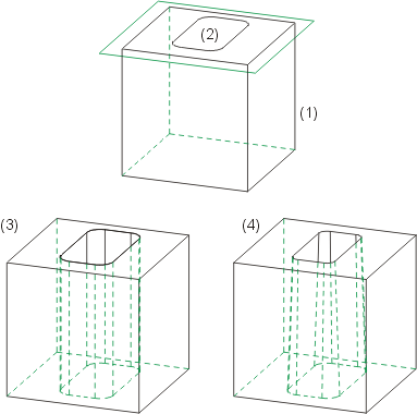
(1), (2) Cuboid with sketch (3) Bore, (4) Bore with draught (form-inclination)

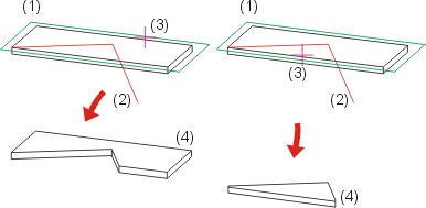
(1) Original part, (2) Open sketch, (3) Side to be cropped, (4) Result

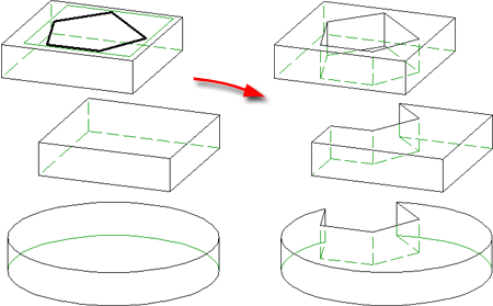
Left: Sketch, multiple selection; Right: Result
Click  to open a menu with further functions for the creation of subtractions or part divisions:

|
Subtract part, with translation + depth |

|
Delete subtraction |

|
Divide with sketch |
![]() Please note:
Please note:
- The name of the 3-D part is retained as the part name. If the sketch projects beyond the bounding edges of the 3-D part, it is cropped or, in the least favourable case, sliced. If the sketch completely overlaps the 3-D part, a dummy part is created.
- The direction in which subtractions and additions are applied depends on the current sketch plane.

"Process with Sketch" Dialogue Window (3-D) • Working with Sketches (3-D)
