![]()
![]()
The Steel Engineering settings that were previously specified in the system file STB_PARAMETER.DAT have been moved to the Configuration Editor. There, you can find the settings at Steel Engineering and Compatibility.
Therefore, the corresponding settings have also been removed from the Steel Eng. Settings dialogue window.

![]()
The settings of the files SSTINI.DAT and SSTINI3D.DAT are no longer relevant for HiCAD and are therefore no longer available.
![]()
The settings for Management + BIM have been rearranged. You can still find them at PDM > Management + BIM.
![]()
The parameters at Steel Engineering > DSTV-NC
have been moved to the export dialogue.
![]()
During the data transformation between IFC and HiCAD the attribute values from the original data will be transferred to permissible attribute values of the target system. The rules according to which the Attribute mapping configuration is to be carried out can be defined for the import and the export of IFC files at Interfaces > IFC.
![]()
When generating detail drawings according to the settings at Management + BIM you have the option to transfer article attributes of semi-finished products to the to document attributes of detail drawings. These document attributes can, for instance, be used in HELiOS result lists as filters or search criteria.
The assigning takes place at PDM > Management + BIM > Production drawings > Transfer article attributes.
You have now the option to create CAM data for the production of the parts in the production drawings of the current model drawing, and to mange and link them in HELiOS. This can be done for the formats DSTV-NC, NCW, DXF and STEP.
Whether the creation of the CAM data takes place manually or automatically can be specified at PDM > Management + BIM > External production drawings.
You have now the option to automatically create NCW data for part and to manage and link them in HELiOS.
A prerequisite for the creation of this file format is that the parameter Create NCW/NCX data at PDM > Management +BIM > External production drawing has been set to Yes. The default setting is No, i.e. no NCW data are normally created.
You have now the option to automatically create DWG files for production drawings, either upon
of the drawings. For this purpose, the settings at PDM > Management + BIM > External production drawings have been expanded accordingly.
The new Clean up function (in the Project function group) cleans up the active project by detecting and deleting invalid article masters.
Using this function only makes sense if the parameter Clean up project when saving at PDM > Management + BIM has been set to No. The default setting is Yes, i.e. whenever you save your drawing, invalid article masters will be removed automatically.
The HELiOS attributes SACHNUMMER (Article number) and BENENNUNG (Designation) can be created from template files, if the parameter Create HELiOS attributes from FTD file in the Configuration Editor at PDM > Management + BIM > Production drawingshas been set to Yes. The editing of these templates previously took place via the Steel Engineering function Part annotation templates. As of HiCAD 2016 SP2 you use the new Templates, Attribute assignment function for this. You can find the function at Steel Engineering > Further functions > Settings  > ....
![]()
Boltings in production drawings can be hidden via appropriate settings in the Configuration Editor. You can specify for each usage whether bolts are to be shown or hidden. The corresponding settings can be found at Automatic drawing derivation > Production drawing > Usage-dependent > name > Views (with name being the name of the respective usage).
![]()
Use the Include new parts in list views of mounting drawings parameter at System settings > Visualisation > Views to specify whether created new parts will be shown or hidden upon updating of a mounting drawing.
![]()
The settings of the system file PARAMASS.DAT for parametric dimensions and the representation of HCM symbols have been moved to the Configuration Editor. They can now be found at
The changes in the Configuration Editor will only take effect after a restart of HiCAD.
![]()
The handling of manually assigned article masters when exchanging semi-finished materials can be defined in the Configuration Editor at System settings > HELiOS - Handling of article master.
The collection of the Taking over of semi-finished product attributes parameter will be evaluated in the process.
 Please note:
This parameter will not be considered for the exchanging of Sheet Metal parts via feature.
![]()
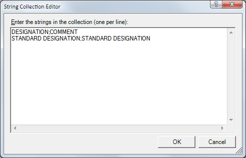
At Taking over of semi-finished product attributes (System settings > HELiOS > ...) you can specify whether particular semi-finished product attributes are to be assigned to the manually assigned article attributes during exchanging of semi-finished products. Each assignment is defined in one row:
Semi-finished product attribute;Article attribute.
![]()
The parameter Automatic ViewAll (System settings > Visualisation) has been renamed to Automatic ViewAll after projection change. The dialogue texts have also been changed.
![]()
You can specify in HiCAD whether . The default setting is Scale-independent. With this setting, the spacing between the hatching lines will always be the same, no matter which scale was selected.
The default setting shown in the dialogue window can be changed in the Configuration Editor, at System settings > Visualisation > Scale dependent 3-D hatching.
![]()
The XML-based accompanying format PLMXML is a supplement to the JT interface. It allows the defining and storing of product structures and process data of complex assemblies in a readable form. Import and export options are handled in the same way as in the JT interface.
Which export functions are to be activated or deactivated upon function call can be specified in the Configuration Editor, at Interfaces > JT/PLMXML.
![]()
The settings of the file ANSGEN.DAT that contains setting options for views can now be found in the Configuration Editor. There, the settings for views can now be found at:
New is the possibility to specify the settings separately for sectional and detail views, and that the representation (colour, line type and layer) of view group frames can now be specified for derived drawings.
![]()
The following functions have been added to the toolbar of the Configuration Editor:
|
|
Collapse all |
This function collapses the structure display of the Configuration Editor and shows only the 1st level. |
|
|
Expand 2 levels |
Shows you the first 2 levels of the configuration structure. |
|
|
Expand 3 levels |
Shows you the first 3 levels of the configuration structure. |
|
|
Expand all |
Expands the complete structure display of the Configuration Editor. |
![]()
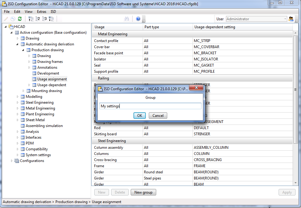
In some areas you have the options to add new data records, or new groups with data records. To do this, click the New group button, enter a name and click OK. The group will then be added and an empty data record entry will be shown. When you now click on the input fields, you can compose the data record from the values in the displayed selection boxes.
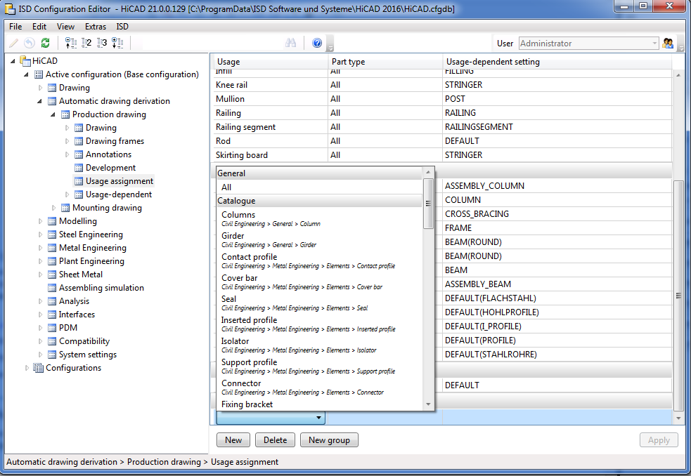
Confirm your entries with Apply.
Use the New and Apply buttons to add data record also to already existing groups.
To remove a data record, mark it and click the Delete button. Click Apply to confirm the deletion.
![]()
You now distinguish between Production drawing and Mounting drawing. As a result, the tree structure has changed here.
The assigning of usage-dependent settings has been simplified and enhanced.
At Automatic drawing derivation > Production drawing > Usage-dependent > …. > Views > Shortened view you will find the new General view shortenings section. The settings will now be loaded from the Configuration Editor not only for the views of beams and profiles, but also for other views, e.g. sheet views etc.
In HiCAD 2015, standard parts were annotated if you explicitly activated the annotation of sub-parts or (as of SP1) the annotation of boltings. As of HiCAD 2016 the annotation of standard parts can be switched on or off, independent of other annotation types.
If the settings for drawing derivation are loaded from a configuration, the settings specified in the Configuration Editor at Automatic drawing derivation > Production drawing > Usage-dependent > name > Views > Shortened view will be evaluated. name denotes the name of the corresponding usage.
A new listbox for frames and view groups offers the following selection options:
The default setting is Always insert. This presetting can be changed in the usage-dependent templates in the Configuration Editor at: Automatisc drawing derivation > Production drawing > Usage-dependent > ... > View groups > Frames around view groups.
If a drawing frame contains only one view group, it will be centred in the drawing frame. This behaviour, too, can be changed in the Configuration Editor, at Automatic drawing derivation > Production drawing > Drawing > Centre individual view group. If you deactivate the checkbox, individual view groups will be placed at the top left of the drawing frame instead.
Colour, layer and line type of the frames can be specified in the Configuration Editor at System settings > Visualisation > View group.
![]()
When creating drawing derivations, you can distinguish between "Mounting" and "Workshop" for semi-finished products.
The relevant parameters can be found in the Configuration Editor, at PDM > Management+BIM > Individual part type.
For production drawings you have now the option to create DXF and PDF files either
of the drawings. For this purpose, the Configuration Editor now offers additional setting options at PDM > VManagement + BIM.
For production drawings you have now the option to create DXF and PDF files either
of the drawings. For this purpose, the Configuration Editor now offers additional setting options at PDM > Management + BIM.
![]()
The presettings for part edge representation during loading of referenced parts in sectional views, detail views and cut-outs have been changed. Colour, layer and line type can now be set at System settings > Referencing - Updating.
![]()
The settings of the vertical and the horizontal hatching angle are now calculated automatically for the sake of an optimal visual representation. The previous input fields for manual settings have been removed. However, if you prefer to use other hatching angles, you can still do this by specifying the desired angles in the Configuration Editor, at Plant Engineering > Isometry and Pipe spool drawing - Dimensioning.
![]()
When a symbol is added to a P+ID, HiCAD will check whether a DMO filter matches this symbol. If this is the case, the attribute values of the corresponding template will be copied to the attributes of the symbol.
If you do not want this, you can either remove all DMO filters from the object, or globally deactivate this mechanism via Plant Engineering > P+ID > Use DMO filter during symbol insertion.
![]()
In Metal Engineering, a purpose will be automatically assigned to sketches. One distinguishes between Purpose = Part and Purpose = Create /Edit.
In the Configuration Editor, at System settings > Sketches > Purpose for new sketches in ME grid (for a working with the Metal Construction plugin) you can specify which of the two purposes is to be assigned when a new sketch is created.
![]()
You can specify that sheets and thread bodies are to be unioned via Interfaces > General 3-D interfaces > Thread body and ... Unite sheets.
Thread bodies can be exported as Separate parts or can be United with the parent part during export.
Select Unite sheets if you want all sub-parts of a sheet and the superordinate part to be combined into one part during export.
![]()
Related Topics
Configuration Management (CM) • User Interface (CM)
|
Version 2102 - Configuration Management | Date: 07/12/2016 | © Copyright 1994-2016, ISD Software und Systeme GmbH |


