HiCAD supports a part classification according to freely definable usages. You can, for example, define parts as columns, girders, mullions, transoms etc. This classification takes place by selecting the Part attributes function and assigning the Usage attribute to the part. This will enable you to create Usage-dependent workshop drawings, i.e. you can, for instance, individually specify dimensioning rules for the different usages.
The configuration takes place in the Configuration Editor, the definition of new usages in the Catalogue Editor.
![]()
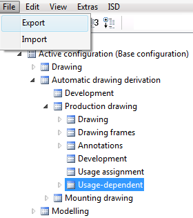
All settings that are relevant for the generation of detail drawings and workshop drawings are specified in the Configuration Editor and saved to the configuration database HICAD.cfgdb in the CONFIGURATION directory of your HiCAD installation. This database (or parts of it) can be imported and exported. The settings for detail drawings and workshop drawings can be found at Automatic drawing derivation.
For instance, if you want to import only the Usage area, mark it and select File > Import.
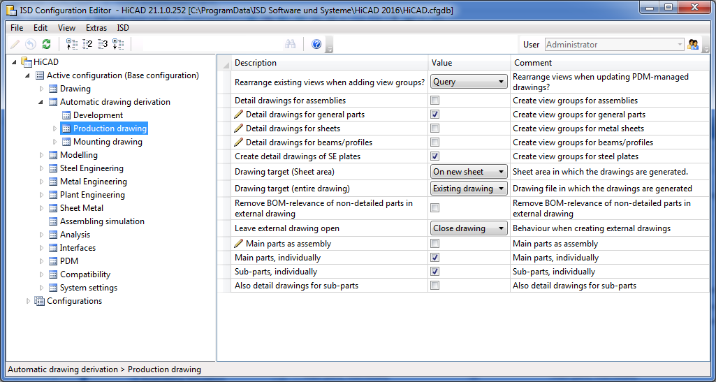
At Automatic drawing derivation you can specify general settings for the generation of detail drawings and workshop drawings. Basically, these are the presettings for the Derived drawing dialogue window.
At Automatic drawing derivation > Production drawing > Drawing you will find pre-settings options for the Settings for Drawing Sheets dialogue window.
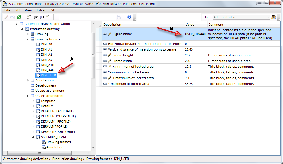
Here you will find all drawing frames that can be selected for the derived drawing and various setting options for them. Please note that you can also specify HiCAD or Windows paths here, namely, via the Figure name parameter. In the Value field, you can precede the figure name by a path.
Examples:
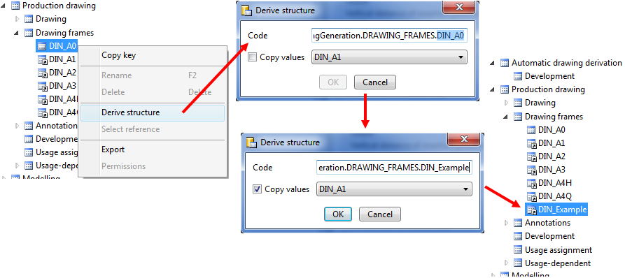
If you want to add further drawing frames for workshop drawings, proceed as follows:
Create the 2-D geometry of the new drawing frame. This can be easiest achieved by copying an existing drawing frame and changing the copy (e.g. DIN_Example) of this drawing frame.
Start the Configuration Editor and right-click the DIN_A0 drawing frame.
Select Derive structure.
In the Code field, replace the string DIN_A0 with the name of the new drawing frame, e.g. DIN-Example. If you want to copy the settings of other drawing frame for this new frame, activate the Copy values checkbox.
Then, adjust the settings for the new frame as required, notably the Figure name field.
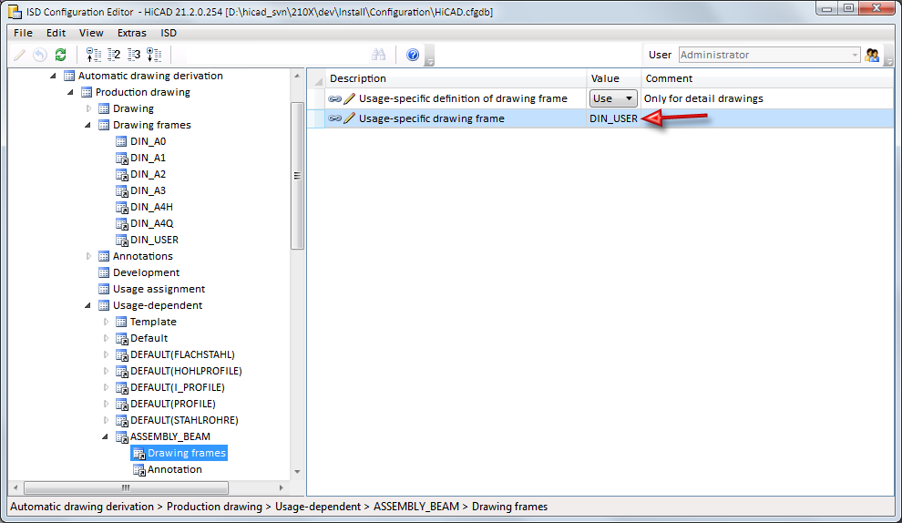
For the output of detail drawings you can also specify usage-dependent drawing frames. At Usage-dependent you can define a usage for the corresponding area of the drawing frame.
For the parameter Usage-specific drawing frame you need to enter the name A specified beneath Drawing frames in the structure tree, and not the name of the figure file B!
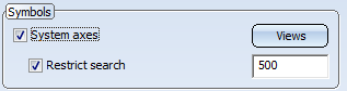
The settings for Grid annotation determine the representation of system axes in the workshop drawing. This means that if in the Settings for views dialogue window the System axes checkbox has been activated, these settings will be taken into account.
These settings refer to sheet metal developments in workshop drawings. For example, you can specify the development method, the representation of bend lines and bend line texts here.
HiCAD supports a part classification according to freely definable usages. You can, for example, define parts as columns, girders, mullions, transoms etc. This classification takes place by selecting the Part attributes function and assigning the Usage attribute to the part. For many functions, this happens automatically, e.g. for railing configurations. For a manual assigning of a Usage, you use the Part attributes in the context menu for 3-D parts.
The usages are defined in the Factory standards catalogue. To each Usage a configuration key (CONFIGKEY) is assigned there.

For the creation of usage-dependent workshop drawings you can assign to each usage a usage-dependent configuration in which the parameters for the drawing derivation are specified. If desired, the assignment can also be limited to particular part types. The usage is assigned at ..> Automatic drawing derivation > Production drawing > Usage assignment (Key name: WSD_USAGEMAP).
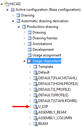
For example, the configuration RAILING is assigned to the usage Railing there, the configuration STRINGER is assigned to the usage Handrail etc. The configurations themselves can be found at Automatic drawing derivation > Production drawing > Usage-dependent, e.g. the configuration RAILING.
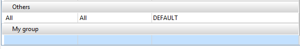
The usages can be neatly arranged into groups. Predefined are the groups
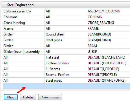
The groups are shown sorted in alphabetical order. The image below shows the ISD default settings. The default entry in the Others group means that the setting DEFAULT will be assigned to all usages that do not occur in the other groups - independent of the part type.
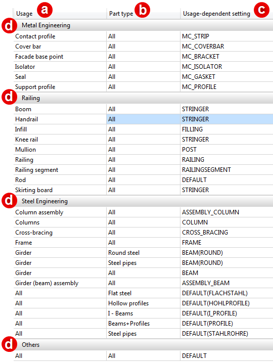
a) Usage, b) Part type, c) Assigned, usage-dependent setting, d) Group
Usage
Here you select the usage to which you want to assign a usage-dependent setting. The definition of new types of use takes place via the Catalogue Editor.
Part type
If the usage assignment is to apply only to particular part types, you can specify in the corresponding field in the Part type column that the assignment is to apply only to assemblies, only to Sheet Metal parts, or only to particular catalogues. For example, if the usage-dependent setting STRINGER is to be assigned only to Handrails of the type Flat steel, select the Flat steel entry in the corresponding field of the Part type column.
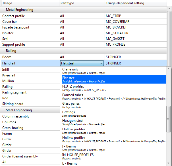
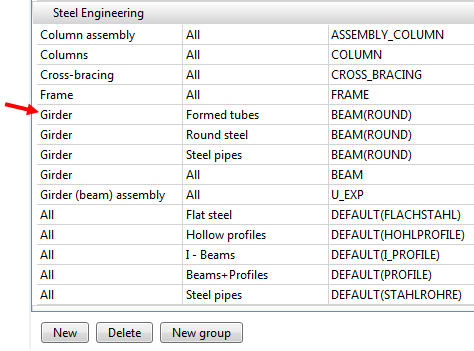
In this way, several assignment rows can exist. Identical usages are arranged in direct succession in the list, with the part type All coming last.
One example of this is the usage Girder.
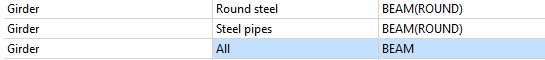
Here, the setting BEAM (ROUND) is assigned to the usage Girder, if the part type is Round steel or Steel pipes. To all other part types, the setting BEAM will be assigned.
Usage-dependent setting
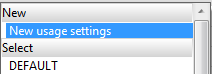
Here you select the usage-dependent setting that you want to assign to the usage and to the part type. Choose the New usage settings from the selection box to define new usage-dependent settings.
The Derive structure dialogue window will be displayed:
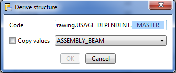
Replace the marked string with the name of the new usage. If you want to apply the values of an already existing usage, activate the Copy values checkbox and choose the desired usage.
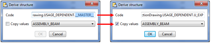
Close the dialogue window with OK.
The new usage setting will be entered in the Usage-dependent setting field and will be immediately visible in the structure tree of the Configuration Editor.
The buttons below the list have the following meaning:
|
New |
Click this button to define a new assignment. An empty row will be created within the current group, e.g.:
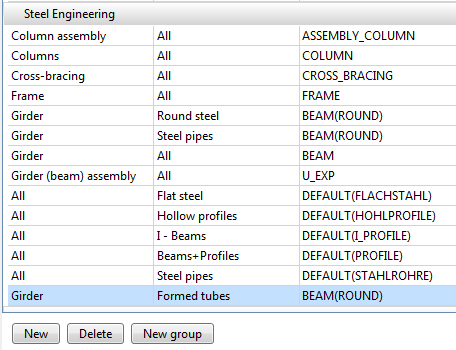
Specify the desired settings, e.g.:
Click Apply to save the applied change. The new entry will then be visible:
|
|
Delete |
Deletes the currently selected assignment. Click Apply to confirm the deletion. |
|
New group |
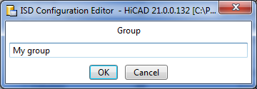
Usages can be neatly arranged into groups. To create a new group, click the New group button.
Enter the name of the new group and confirm with OK. The group will be added and an empty assignment row will be created.
Specify the new assignment and confirm with Apply. |
|
Apply |
Each change to the assignment list needs to be confirmed with Apply in order to take effect. |
 To edit the list of assignments and define new usage settings, the user Administrator needs to be active.
![]()
Here you can find the configurations for the various usages. in each configuration, the corresponding are defined.
A particular feature is the parameter Perform drawing derivation, which you can directly set for the chosen Usage. You can use this parameter to specify for the current usage whether view groups are to be created in the drawing derivation process.
In addition, you can specify here
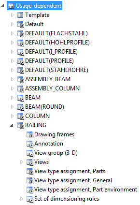
You can also specify usage-dependent drawing frames for detail drawings that are exported to an external drawing file. Beneath Usage-dependent you can define, via the corresponding Drawing frames entry, the drawing frame for this usage.
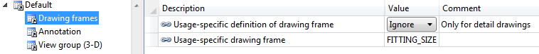
To be able to use the desired drawing frame you need to change both parameters accordingly., e.g. as follows:
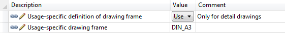
For the parameter Usage-specific drawing frame you need to enter the name A specified beneath Drawing frames in the structure tree, and not the name of the figure file B!
 Important:
must be chosen as the Drawing target for the derivation.
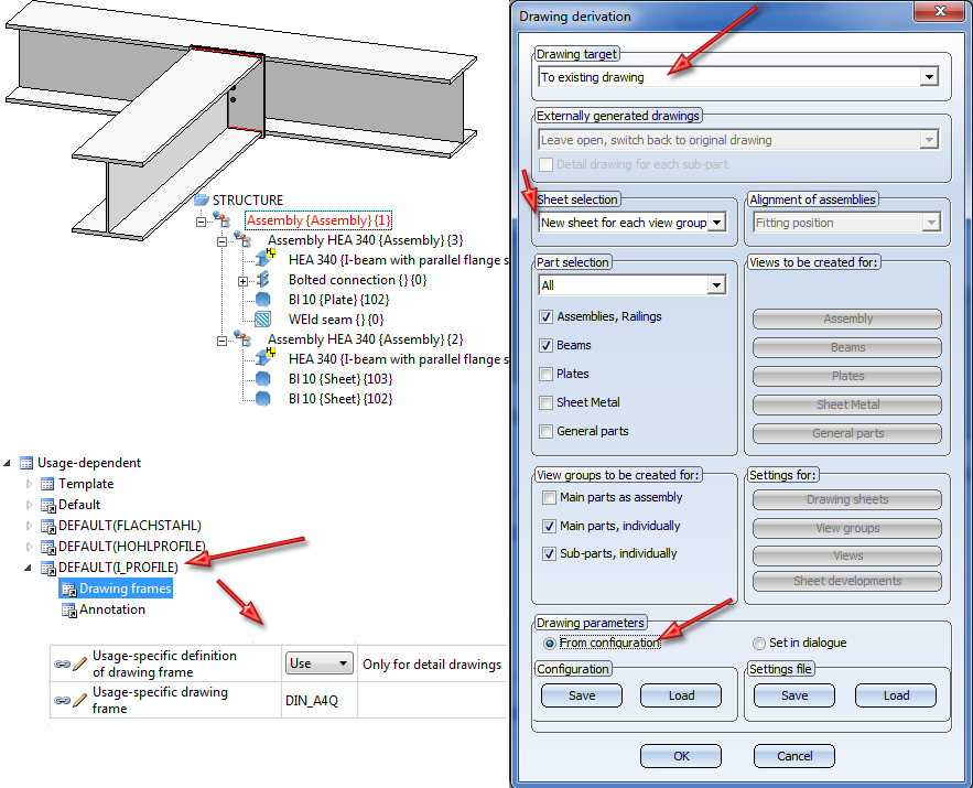
Example:
The image below shows a drawing consisting of two connected I-beams (HEA) and the associated part structure in the ICN. In the Configuration Editor, a Usage-specific drawing frame (DIN_A4Q) has been selected. When you perform a drawing derivation with the settings and options shown below, the drawing frame that was chosen in the Configuration Editor at DEFAULT(I_PROFILE), i.e. DINA4Q, will be used only for the detail drawings of the of the beams.
Another special feature is the definition of dimensioning rules, as these are always loaded from the Configuration Editor - even if the Set in dialogue option is active in the Drawing derivation dialogue. If you do not want any dimensioning rules to be used, this must be changed accordingly in the Usage configurations, at ..> Automatic drawing derivation > Production drawing > Usage-dependent > NAME > Views, with NAME being the name of the corresponding Usage, e.g. RAILING. You can then use the Create dimensioning parameter to specify that:
The definition of dimensioning rules for usages takes place at ..> Automatic drawing derivation > Production drawing > Usage-dependent > NAME > Set of dimensioning rules, with NAME being the name of the corresponding usage, e.g. RAILING.
Although the dimensioning rules can also be changed directly via the Configuration Editor , we recommend using the HiCAD Dimensioning Rule Editor for the easiest and most convenient handling.
Click here for an overview of the available dimensioning rules.
![]()
Related Topics
Derive Drawing • Drawing Derivation • The 'Derived Drawing' Dialogue Window • Configuration Management
|
Version 2102 - HiCAD Steel Engineering | Date: 15/11/2016 | © Copyright 1994-2016, ISD Software und Systeme GmbH |