
Drawing > Itemisation/Detailing > Drawing derivation
If you right-click an assembly, a general 3-D part, a Steel Engineering beam, a Sheet Metal part, or a Steel Engineering plate and select Properties > Alignment of derived drawings you can specify
 or the top view
  , or
, or  .
. Multiple selections are also possible here.
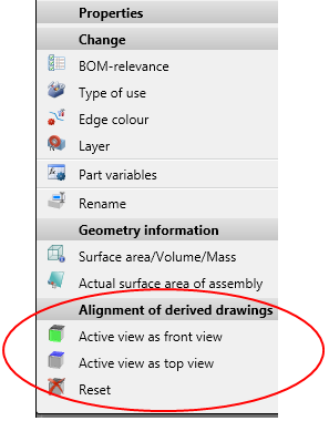
Please note that the chosen option also affects derived drawings!
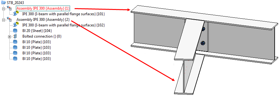
Example:
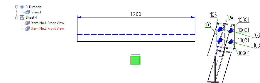
Let us assume that you want to create a workshop drawing for the model drawing shown below.
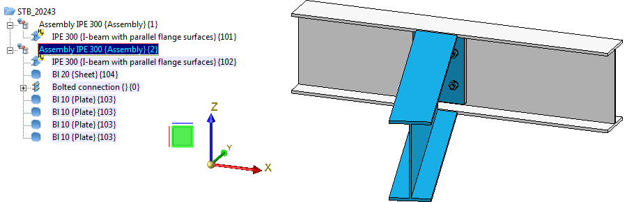
Apply the Active view as front view function to the second assembly (beam, plate and bolting). This will be marked accordingly in the model drawing:
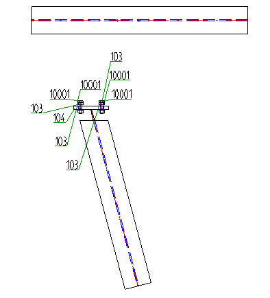
Now, create the workshop drawing:
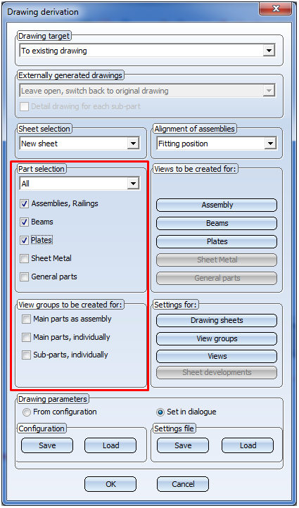
In this example, the front view has been chosen everywhere.
The view selected for the second assembly with the Active view as front view will be considered in the workshop drawing. Here, too, this will be indicated accordingly.
If you now select Reset, the workshop drawing will look as follows:
 Important:
or the Active view as top view function to Steel Engineering plates, HiCAD will check whether the new alignment of the beam/plate is actually allowed. Please note the following:
The result of the check will then be shown in a dialogue window. Here it will be listed for which of the chosen plates the new alignment was successful, and to which no new alignment could be applied.
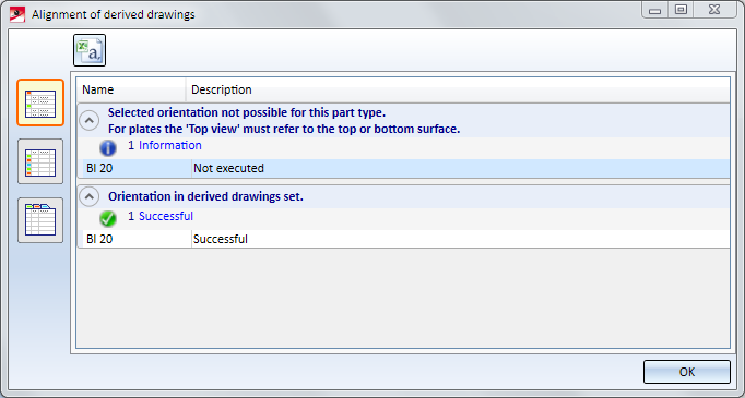
Use the symbols on the left to switch between the following representations of the list:
 Detailed list
 Abridged list
 List with several tabs
Click the  symbol to save the result list as a CSV file.
![]()
Related Topics
Derive Drawing • Drawing Derivation • The 'Derived Drawing' Dialogue Window • Usage-Dependent Configurations
|
Version 2102 - HiCAD Steel Engineering | Date: 15/11/2016 | © Copyright 1994-2016, ISD Software und Systeme GmbH |