Management + BIM > Drawing > AutoCreate/Update
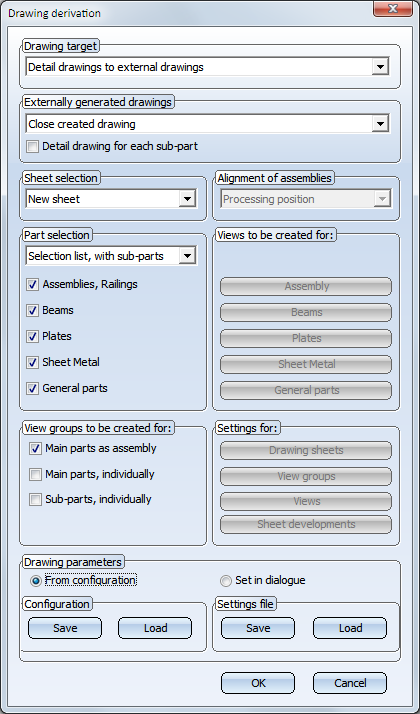
Use this function to automatically create and update drawings. In contrast to the Create/Update Drawing - Manual  function, the settings for drawing derivation (i.e. for drawing sheets, views, view groups etc.) will not be queried in the dialogue, but loaded from the corresponding settings files. This means that the Drawing derivation window will not be displayed here. In this way, drawing creation can be speeded up.
When you call the function, HiCAD will check
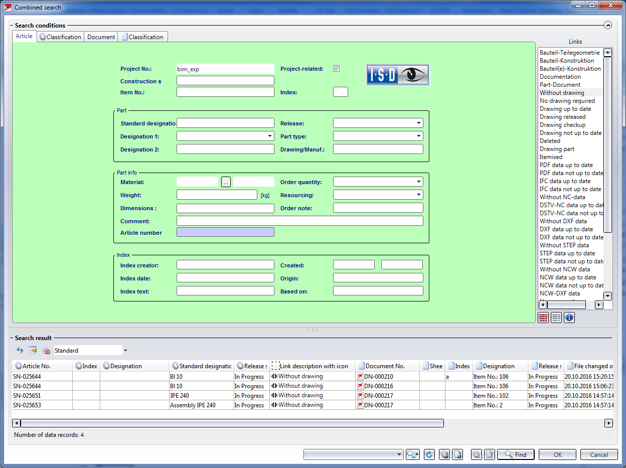
The result of the search will be shown in the Combined search mask of the HELiOS Desktop. Here, all parts of the model drawing with the links
will be shown.
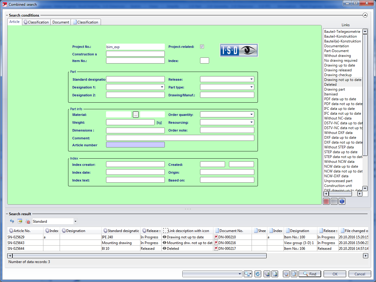
Select the parts for which a drawing is to be created (or updated), and click OK. The selected parts will be highlighted in the model drawing and the following message appears:
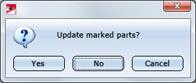
When you select OK, the drawings for the highlighted parts will be updated or deleted.
Then, all parts with the "Without drawing" link (i.e. all parts for which no production drawing exists yet) will be listed. Non-existent mounting drawings will not be considered here.
Now, select the parts for which you want to create production drawings and confirm with OK. The selected parts will be highlighted in the drawing and the following message appears:
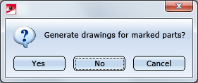
Click Yes to create the drawings for the selected parts. Inputs in the Drawing derivation window are not required here, since the settings for drawing derivation will be loaded from the appropriate presetting files here.
The workshop drawing will be created immediately as a Sheet view - either in the original model drawing or in a new drawing. Sheet views of the current model drawing can be opened in the Views tab of the ICN.
By default, the following template files are supplied with HiCAD(in the SYS directory):
|
File |
Settings for | |
|---|---|---|
|
BIM_WSD_Default_Assembly.DAT |
Assemblies |
|
|
BIM_WSD_Default_IndividualPart.DAT |
Individual parts
|
|
|
BIM_WSD_Default_Bolted_Assembly.DAT |
Bolted assemblies (Site) |
|
|
BIM_WSD_Default_Welded_Assembly.DAT |
Welded assemblies (Workshop) |
|
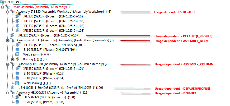
In the supplied settings files, the drawing parameters will be specified via configuration, i.e. the settings in the Configuration Editor at Automatic drawing derivation > Production drawing > Usage-dependent will be used. This means:
Example:
 Please note:
 function.
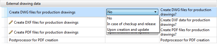
If the setting In case of checkup and release has been chosen for the Create ... files for production drawings parameters beneath External drawing data, the corresponding DXF, DWG or PDF files will be created for the production drawings. Please note that a Postprocessor needs to be specified for PDF files.
![]()
![]()
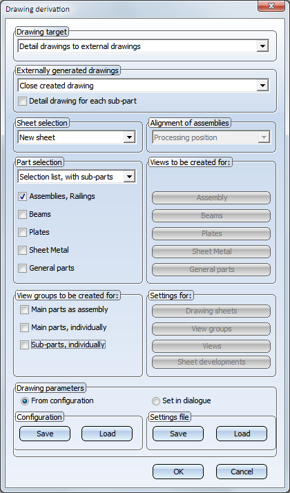
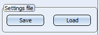
Besides the option to use the predefined settings files supplied with HiCAD, you can also create, depending on the respective usage/part type, your own settings files. To create or modify such files, select Drawing > Itemisation/Detailing > Derive  . Specify the desired settings in the dialogue. To Save the settings in a settings file, or to Load an existing file, use the buttons beneath Settings file.
The files must be given the following names:
with UsageText standing for the designation in the tables of the Factory Standards catalogue Usage, and UsageKey standing for the CONFIGKEY.
|
Catalogue |
Table |
UsageKey = CONFIGKEY |
UsageText = Designation |
|---|---|---|---|
|
General |
Column |
COLUMN |
Columns |
|
Girder |
BEAM |
Girder |
|
|
Metal Engineering - Elements
|
Contact profile |
MC_STRIP |
Contact profile |
|
Cover bar |
MC_COVERBAR |
Cover bar |
|
|
Seal |
MC_GASKET |
Seal |
|
|
Inserted profile |
MC_INSERTIONBAR |
Inserted profile |
|
|
Isolator |
MC_ISOLATOR |
Isolator |
|
|
Support profile |
MC_PROFILE |
Support profile |
|
|
Connector |
MC_CONNECTOR |
Connector |
|
|
Metal Engineering - Groups |
Fixing bracket |
BEFESTIGUNGSKONSOLE |
Fixing bracket |
|
Inserts |
MC_LOGIKALOBJECT |
Insert |
|
|
Top or base point |
MC_BRACKET |
Facade base point Facade top point |
|
|
Mullion |
MC_MULLION |
Mullion |
|
|
Mullion connection |
PFOSTENSTOSS |
Mullion connection |
|
|
Transom |
MC_BAR |
Transom |
|
|
Steel Engineering - Assemblies
|
Stabilizing pipe |
STABILIZING_PIPE |
Stabilizing pipe |
|
Cross-bracing |
CROSS_BRACING |
Cross-bracing |
|
|
Steel frame |
FRAME |
Frame |
|
|
Welded beam/profile |
WELDED_I_SECTION |
Welded I-beam |
|
|
WELDED_BOX_SECTION |
Welded box profile |
||
|
WELDED_CROSS_SECTION |
Welded cross-profile |
||
|
WELDED_SEMICROSS_SECTION |
Welded cross-profile, half |
||
|
Column assembly |
ASSEMBLY_COLUMN |
Column assembly |
|
|
Girder (beam) assembly |
ASSEMBLY_BEAM |
Girder (beam) assembly |
|
|
Steel Engineering |
Plate types |
FILLER-PLATE |
Filler plate |
| BASE-PLATE |
Base plate |
||
|
TOP-PLATE |
Top plate |
||
|
STIFFENER |
Stiffener |
||
|
REINFORCEMENT-PLATE |
Reinforcement plate |
||
|
Railing |
SKIRTING |
Skirting board |
|
|
WEBMEMBER |
Rod |
||
|
FILLING |
Infill |
||
|
RAILING |
Railing |
||
|
RAILINGSEGMENT |
Railing segment |
||
|
STRINGER |
Boom |
||
|
HANDRAIL |
Handrail |
||
|
KNEERAIL |
Kneerail |
||
|
POST |
Post |
Alternatively, you can also use part types: BIM_WSD_PartType.DAT
For example, if you require particular settings for I-beams, you need to create a BIM_WSD_I - Profile.DAT file.
| Part type | Catalogue | Part type | Catalogue |
|---|---|---|---|
|
A1 Girder |
Factory standards > Factory beams > Frankstahl |
Glass panes |
Factory standards |
|
A3 Steel bar |
Factory standards > Factory beams > Frankstahl |
Hollow profiles |
Factory standards > Factory beams > Frankstahl > A4 Shaped tubes, Hollow profiles, Profiles |
|
General |
Factory standards > Usage > Civil Engineering |
Wood |
Semi-finished products |
|
B1 Commercial tubes, seamless |
Factory standards > Factory beams > Frankstahl |
IN-HOUSE_PROFILES |
Factory standards > Factory beams |
|
B2 Commercial tubes, welded |
Factory standards > Factory beams > Frankstahl |
Cold-rolled sections |
Semi-finished products |
|
B4 Mechanical stress-resistant steel pipes |
Factory standards > Factory beams > Frankstahl |
Crane rails |
Semi-finished products > Beams+Profiles |
|
B5 Precision steel pipes |
Factory standards > Factory beams > Frankstahl |
L - beams |
Semi-finished products > Beams+Profiles |
|
B6 Hydraulic components |
Factory standards > Factory beams > Frankstahl |
Profiles |
Semi-finished products Factory standards > Factory beams > Frankstahl > A4 Shaped tubes, Hollow profiles, Profiles |
|
Reinforced steel |
Semi-finished products > Beams+Profiles |
Round steels |
Semi-finished products > Beams+Profiles |
|
Plates |
Semi-finished products |
Hexagonal steels |
Semi-finished products > Beams+Profiles |
|
C-beams |
Semi-finished products > Cold-rolled sections |
Steel pipes |
Semi-finished products > Beams+Profiles |
|
C1 Pipes and Profiles |
Factory standards > Factory beams > Frankstahl |
T - beams |
Semi-finished products > Beams+Profiles |
|
C3 Stainless steel bars |
Factory standards > Factory beams > Frankstahl |
U - beams |
Semi-finished products > Beams+Profiles Semi-finished products > Cold-rolled sections |
|
Flat steel |
Semi-finished products > Beams+Profiles |
Square steel |
Semi-finished products > Beams+Profiles |
|
FLUTZ profile |
Factory standards > Factory beams |
Voest profiles |
Factory standards > Factory beams |
|
Formed tubes |
Factory standards > Factory beams > Frankstahl > A4 Shaped tubes, Hollow profiles, Profiles |
Z - beams |
Semi-finished products > Beams+Profiles |
|
Gratings |
Semi-finished products |
|
|
During automatic drawing creation HiCAD will check for each usage / part type whether pre-settings already exist, namely, in the following order:
Example:
Let us assume that, besides the default settings flies, the following files exist:
In this case, the settings from the file BIM_WSD_Column assembly.DAT will be used for all assemblies with the usage Column assembly; for all other assemblies, the settings from the default files will be used, i.e. the settings from the file BIM_WSD_Default_Assembly.DAT for general assemblies, and the settings from the files BIM_WSD_Default_Bolted_Assembly.DAT or BIM_WSD_Default_Welded_Assembly.DAT, respectively, for bolted assemblies or welded assemblies, respectively.
For individual I-beams (not part of an assembly), the settings from the file BIM_WSD_I - beams.DAT will be used; for all other individual parts, the settings from the file BIM_WSD_Default_IndividualPart.DAT will be used.
Please note:
 symbol. The referencing is unilateral, i.e. in case of changes to the model, the workshop drawing can automatically be updated. If you want a bilateral referencing, change the setting in the Configuration Editor accordingly.
It is also possible to switch off the automatic rearranging of views. In the Configuration Editor. Select ... > PDM > Management+BIM and set the parameter Rearrange views when updating PDM-managed drawings as required. The default setting is Rearrange.
If an automatically generated article master is not used in a super-ordinate article master, and a part with no links exists, the product structure of the part will be deleted before a general clean-up takes place.
![]()
Related Topics
Derive Drawings (ManBIM) • Basic Procedures (ManBIM)
|
Version 2102 - Steel Engineering Drawing Management (BIM-PDM) | Date: 15/11/2016 | © Copyright 1994-2016, ISD Software und Systeme GmbH |