3-D-Standard > Process with sketch > Deform
Use this function to deform parts by bending them along a defined sketch. The following types of deformation are available:
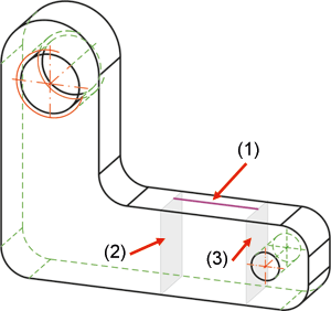
The sketch plane determines the neutral axis for the bending process. This means that the part area to be deformed is determined by the planes (2) and (3) that are vertical to the start point and end point of the sketch (1):
Proceed as follows:
The Deform dialogue window will be displayed. In the drawing, the selected part will be highlighted in green colour.
If mandatory specifications are still missing, the  symbol will be displayed at the bottom of the window. If you move the cursor on the symbol, a message informing you which steps are still necessary before the function can be executed.
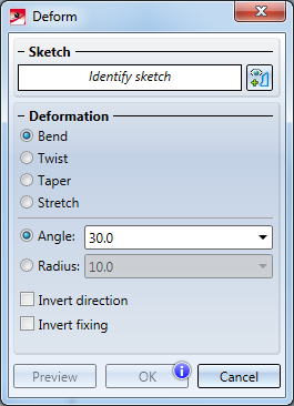
Deformation
In this area you define the type of deformation by activating the corresponding checkbox. Depending on the selected type, the input fields and available options in the Sketch and Invert area of the dialogue window will change.
Sketch
Click the  icon and identify the sketch for the wrapping in the drawing. The sketch needs to fulfil the following criteria:
If a correct sketch has been identified, the Identify sketch prompt will be replaced by the entry Sketch.
Mode
In this area you specify a mode for the selected type of deformation. In the Deformation area of the dialogue window, you can choose between the following options:
| Deformation | Available modes |
|---|---|
|
Bend |
The bending can be performed by specifying the
|
|
Twist |
Angle |
|
Taper |
Factor |
|
Stretch |
The stretching can be performed by specifying either the
If you specify the Distance, the area to be deformed will be stretched/compressed in such a way that it will have the width you specified for Distance. |
When you move the cursor over the different options in the dialogue window, preview images will be displayed:
|
|
|
|
|
|
Bend |
Twist |
Taper |
Stretch |
Invert
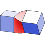
By default, the part area that lies before the start point of the sketch will remain fixed during deforming. The Fixing checkbox enables you to switch the fixing to the exact opposite of the part.
By default, the part will be bent in Z-direction of the sketch in the deforming process. You can use the Direction checkbox to invert the bending direction. This can be applied in a similar way to deformations of the type Twist. Here, the rotation is performed about the X-axis of the sketch. Here, too, you can use the Direction checkbox to invert the rotation direction.
The following options are available:
| Bend | Twist | Taper | Stretch |
|---|---|---|---|
| Direction | Direction | ||
| Fixing | Fixing | Fixing | Fixing |
Click Preview to display a preview of the processed part in the drawing. If desired, you can now change the bending direction by activating the Direction checkbox, switch the side to be bent by activating the Fixing checkbox, or make other changes to the settings in the window. If the operation cannot be performed due to missing mandatory specifications, the symbol will be displayed at the bottom of the window.
The actual operation will be performed when you click the Deform button.
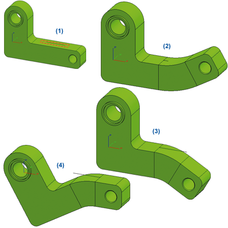
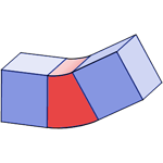
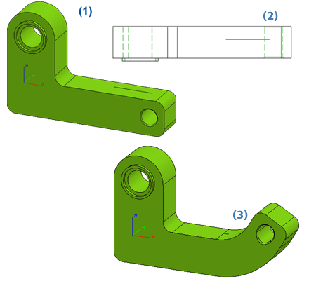
(1) Original part with sketch; (2) Bend angle 30°, (3) Direction checkbox active, Fixing checkbox inactive; (4) Direction checkbox inactive, Fixing checkbox active
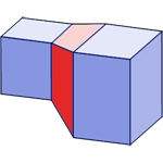
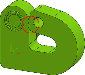
In the image below the sketch has been slightly moved. As a result, the form of the bore will also change in the deformation process:
(1) Original part with sketch; (2) Top view, (3) Deformed part
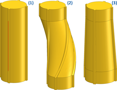
(1) Original part with sketch; (2) Twisting 90°, (3) Tapering with factor 1.2
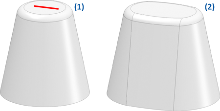
(1) Original part with sketch, (2) Stretching, factor 2
 Please note:
 > 3-D Geometry to check the part.
![]()
Related Topics
Transform and Clone Part (3-D) • Transform Part (3-D) • Referencing (3-D)
|
Version 2102 - HiCAD 3-D | Date: 15/11/2016 | © Copyright 1994-2016, ISD Software und Systeme GmbH |