3-D Standard > New > Solid primitive > Cuboid ![]()
Enter the part name. Activate or deactivate the Reference, Feature and BOM-relevant checkboxes.
Now enter the required data.
|
Type |
Preview |
Points direct |
|
|---|---|---|---|
|
Solid body |
|
|
|
|
Hollow body |
|
|
|
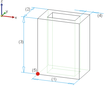
If you have selected the Preview mode, position the cuboid in the drawing. The fitting point is the bottom left corner of the cuboid.
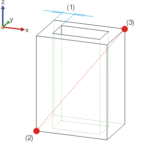
In the Points direct mode,you define the height by specifying the start and end points of the space diagonal, e.g. Absolute (0,0,0) and (0,0,500).

Hollow cuboid in Preview mode: (1) Length, (2) Width, (3) Height, (4) Wall thickness (internal), (5) Fitting point

Hollow cuboid in Points direct mode: (1) Wall thickness (internal), (2) Start point, (3) End point of the space diagonal
![]() In the case of negative value inputs, the corresponding value is marked
off in negative axis direction, e.g. in negative z-direction if you enter
a negative value for the height. This also changes the fitting point (e.g.
with negative height specification – top left corner).
In the case of negative value inputs, the corresponding value is marked
off in negative axis direction, e.g. in negative z-direction if you enter
a negative value for the height. This also changes the fitting point (e.g.
with negative height specification – top left corner).
Related Topics
Solid Primitives (3-D) • Part Creation Functions (3-D)
|
Version 2102 - HiCAD 3-D | Date: 15/11/2016 | © Copyright 1994-2016, ISD Software und Systeme GmbH |