Value Input (General Advice on Formulas and Variables)
Whenever HiCAD requests a value input, you can also use formulas instead of a numeric value. These formulas can contain the permissible mathematical operators and functions etc. Furthermore, you can also use variables within the value input. They are managed in the variable table and can, for example, be changed or deleted there.
Formulas /variables can be used, for example, in point options and value inputs (e.g. height, length, offset thickness).
Using formulas
You can enter formulas directly when creating or processing a part or subsequently in the feature log.
If you want to use a formula instead of a value in the feature log or change an existing formula, activate the value input window by double-clicking the relevant entry in the feature log, e.g. the Height of a part. You can also right-click on the entry to open a context menu and choose Edit formula. This opens the Formula Editor.
Enter the formula. If the formula you enter contains variables, HiCAD asks for the initial value of the variables. Once the entry has been concluded, the formula is displayed in brackets after the value in the feature log.
 Please note the following:
You can use points or commas as separators. In functions with more that one parameter (e.g. distance_points) a semicolon must be used as separator between the parameters. When loading older formulas (older than HiCAD Version 1800) commas will be replaced with semicolons.
Part variables can contain formulas, which in turn refer to other variables. For example for a cuboid, which should be twice as high as wide and twice as wide as long:
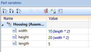
In this case it is sufficient to change the value of the variable length, so that also width and height are adapted automatically:

It may not occur that variables refer cyclically to themselves. Otherwise an error marking is indicated at the variables concerned and the values of the formulas are no longer updated. If you point with the mouse at an error marking, an explanation of the error and the affected variables is displayed:
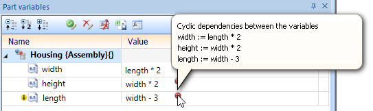
In this case, edit the affected formulas to resolve the cyclic dependency and enable the automatic calculation of the formula values again.
It is also possible to access part variables of any other parts.

Edit variables
The variables used are managed in so-called variable tables.
To activate a variable table, choose one of the following functions:
- Part variables
All variables of a part are displayed.
- Feature variables
Only the variables of the current feature are displayed.
You access these functions by right-clicking a feature or double-clicking in an empty area of the tab. In addition, the Part variables docking window, which always shows the part variables of the active part, is available to you.
The variable table provides the following functions:
- Rename variable,
- Delete variable,
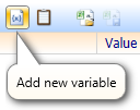
- Add new variable,
- Insert variable,
- Copy variable,
- Cut variable.
To change the value of a variable, proceed as follows:
- Mark the entry and enter the new amount in the input field.
- Double-click the HiCAD pocket calculator to activate it and enter the new value.
The context menu, which you activate by right-clicking a variable name, provides the other functions.
Changes only become active after the Apply all changes button has been pressed. If the Automatic recalculation function is active, this also activates the same function. In order to be able to adjust this option directly, you will find the button Automatic recalculation in the toolbar, which you can use to activate or deactivate it.
![]() Please note:
Please note:
- You use the Copy variable and Cut variable functions to copy the data to text form in the clipboard. You can then insert this data into other programs such as Word, Excel etc.
- Similarly, the Insert variable function transfers the data in the same format. For example, you can use the clipboard to insert data that was saved in a semi-colon separated file in Excel into the variable table.
- The default setting in the feature configuration also applies here to updating the feature model.
- If you mark an element variable, the elements references by it will be highlighted in the drawing.
Example
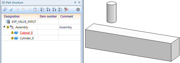
As an example, a model drawing is to be created in which the depth of a material subtraction in one part is determined dynamically based on the position of another part. This is to be done using variables and formulas instead of, for example, HCM constraints.
First, an assembly is created and in this assembly a cuboid and a cylinder are created. In this example the cuboid has the dimensions 500x100x100mm and the cylinder the Height 100mm and the Diameter 50mm.
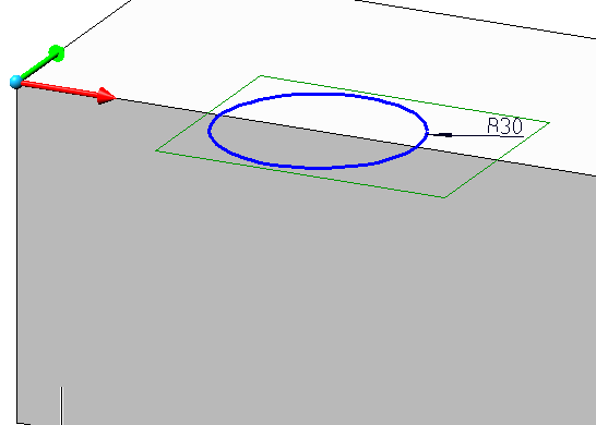
A subtraction is now to be created on the cuboid. This is based on a sketch that is created on the top side of the cuboid and consists only of a circle with a radius of 30mm. The center of this circle is placed on the edge of the box, so that the resulting subtraction is clearly visible:
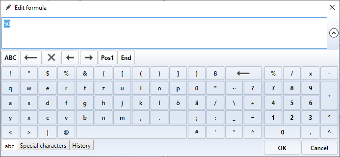
With this sketch, a subtraction is now created in the cuboid. It is important to use the mode "Subtract, via translation" and a Height in -Z-direction of 50 (where any other value can be used).

Now variables are defined. In the 3D Part structure, right-click on the created assembly and select in the context menu the entry Properties> Part variables. The - still empty - Part variables dialogue window opens.

Click the Add new variable button to add a new variable.
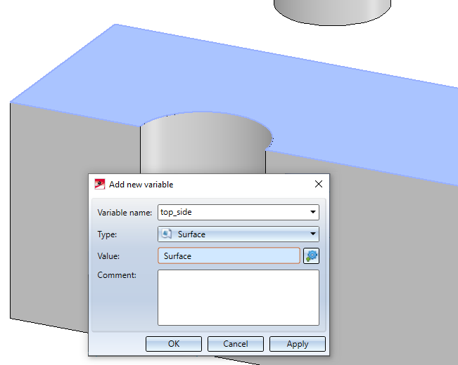
Enter top_side as the Name of the variable, select Surface as the Type and identify the top side of the box:
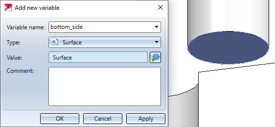
Create another variable from Type: Surface. This time assign the name bottom_side and identify the bottom side of the cylinder:
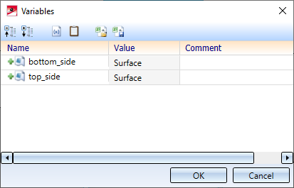
Close the Variables dialogue window by clicking the OK button.
Now place the cylinder in the centre of the subtraction using the functions at 3-D Standard > Transform:

Select the cuboid. In the Feature log, expand the entry Subtract part, via translation and right-click in the line Height / Depth of the value -Z-depth. Select Edit formula from the context menu

The Formula Editor opens.
The goal is to calculate the depth of the subtraction from the distance between the top of the cuboid and the bottom of the cylinder. To do this, we have already assigned these two surfaces to the variables top_side and bottom_side. Now we only have to calculate the value.
To be able to calculate the value, we need a function. To do this, enter distance until you can select distance_faces with autocomplete as shown in the picture below.

The distance_faces function calculates the distance between two surfaces. Select it by double-clicking on it. It will be inserted automatically as a formula:

The variables bottom_side and top_side should be used as parameters. After you have entered (bo , an auto-completion of the variable is offered automatically. You can accept this by pressing the ENTER key.

After a further input of ; to the variable top_side is also offered. Accept this as well (of course you can still enter the variable name manually instead).
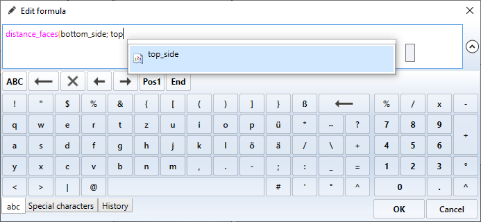
The subtraction should provide an additional distance of 10mm. So finish the formula with ) + 10. The complete formula is:
distance_faces(bottom_side; top_side) + 10

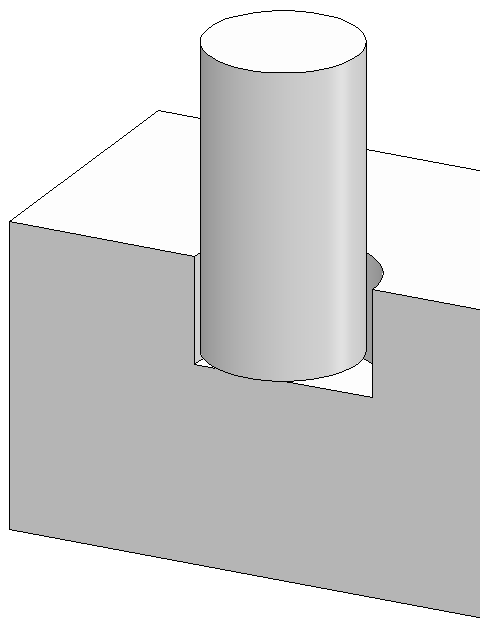
Close the formula editor by clicking OK. The depth of the subtraction is now adjusted to the position of the cylinder:
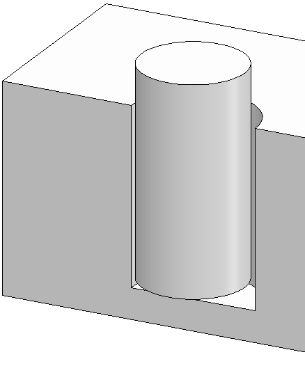
If you change the position of the cylinder, you can now select the assembly and call the Recalculate function to adjust the depth of the subtraction to the changed conditions:
Part or feature variables can be assigned comments in HiCAD for explanation. These can be very helpful, especially if there are a large number of variables. If parts with variables and assigned comments are saved as a VAA file, then you should read the notes in the Comments on variables in variants section.

Feature Technology: Context Menu • Feature Parameter Formulas • Element Variables