Parameterise Part Attributes and Properties
3-D Standard > Tools > Attr...  > Parameterise part attributes
In addition to changing the basic parameters of a part, such as the height of a subtraction or the thickness of a hole, it is also possible to parameterise the attributes and properties of a part. The Parameterise part attributes function is available for this purpose. Call the function in the feature log via the context menu (right-click).
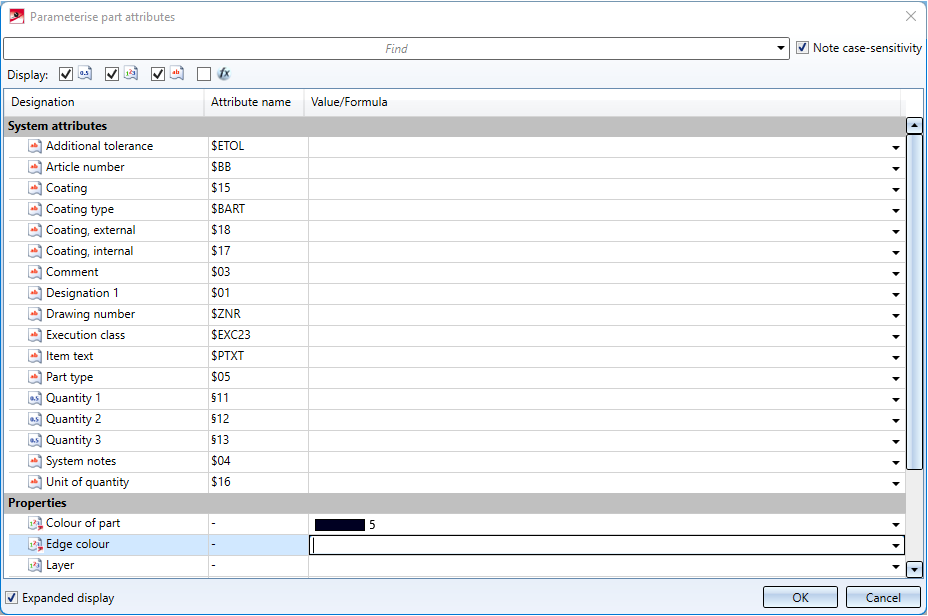
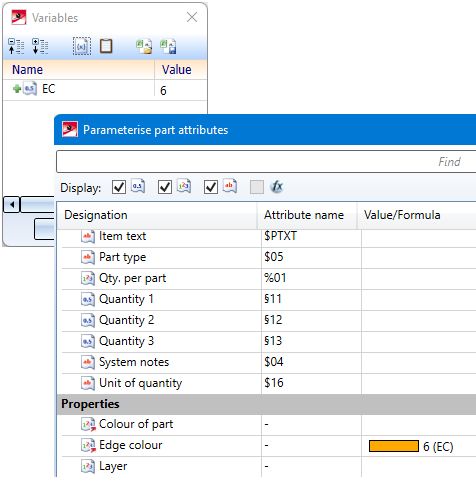
After calling the function, the Parameterise part attributes dialogue window opens:
If the feature log already has a Set attributes entry for the part attributes, you can either modify the existing feature or create a new feature.
You have the option to customise the display of the attributes:
-
Enter a text in the Find field to display only attributes whose name contains that text. If the Note case-sensitivity field is activated, only those attributes are displayed that contain the entered text exactly in the spelling entered; on the other hand, upper and lower case are ignored. If a text is entered in the search field, the Clear filter
 button is displayed next to it. Click this button to clear the search field and display all attributes again.
 -
Next to Display: you have the option of selecting which data types are to be displayed: Here you can determine whether you want to see attributes with the data type Double (floating point numbers), Integer (whole numbers), String (texts) or Formula (value). By default, all data types are selected, i.e. all attributes are displayed.
-
Activate the Expanded display option to have the internal Attribute name displayed in addition to the Designation of the attributes.
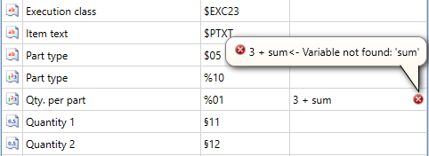
In the Value/Formula column, you can enter a formula that determines the value of the respective attribute. Use the right mouse button to call up the Formula Editor . As soon as you leave an input field (e.g. by selecting another field), the entered formula is checked for plausibility. If it is not correct, an error mark is displayed at the field. If you point to this error mark with the mouse, a description of the error is displayed:
All attributes that have no entry in the Value/Formula field are considered unset and will not be changed by this function.
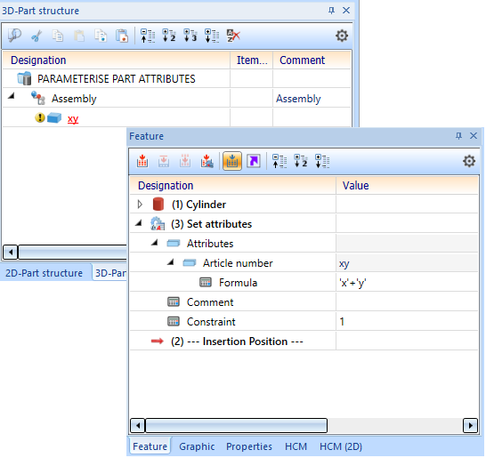
After clicking OK, the feature Set attributes is entered for the part and the attributes are set.
![]() Important:
Important:
You can still freely change the attributes of the part using the Part attributes function. If you select Recalculate, however, the attributes that have been assigned a value in the feature Set attributes are overwritten again.
It is recommended to use the Parameterise part attributes function only for attributes that are actually generated via formulas. Static attributes should still be entered via the Part attributes function.

Edge colour, Line type, Layer
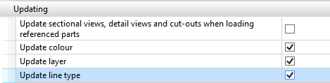
The edge colour of a part, the line type and the layer can also be parameterised. However, this only applies if the corresponding checkboxes are active in the Configuration Editor at System settings > Referencing. This also applies to non-referenced parts!
If you want to parameterise the edge colour, for example, enter either the colour number or a variable, e.g. EC (for Edge Colour), as a constant formula. When using variables, please note that they must be defined beforehand.
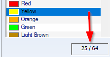
You can see which colour has which colour number in the Colour Editor. The colour number of the selected colour is displayed below the colour list, e.g.:
Material and Usage
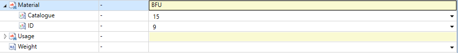
For the parameterisation of the properties Material and Usage, the respective entries Catalogue and ID must be parameterised. These identifiers correspond to the unique assignment in the catalogue
- Catalogue: Corresponds to the Table ID
- ID: Corresponds to the Record ID (cat_item_id)
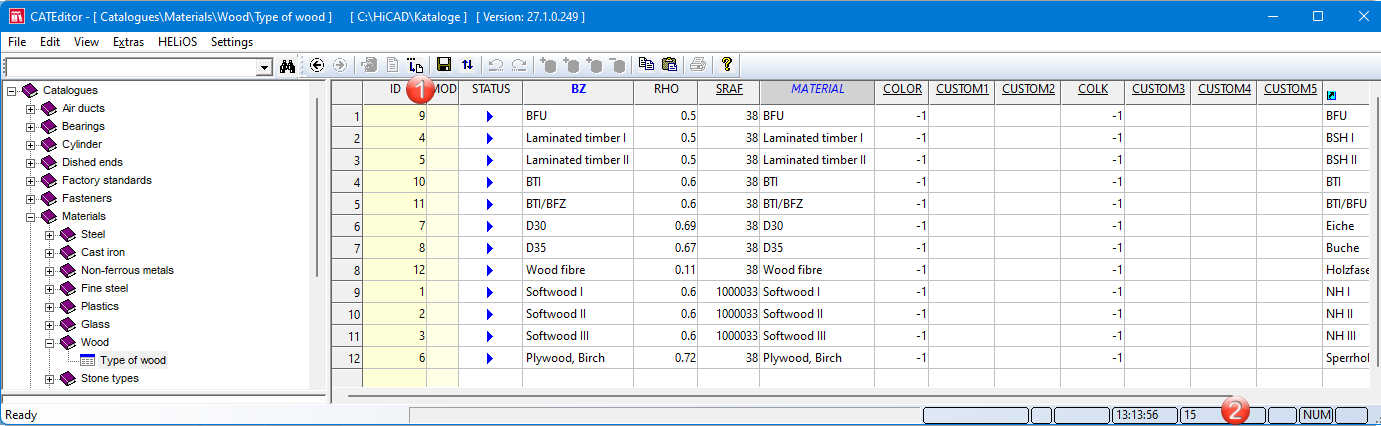
(1) Record ID 9, (2) Table ID 15
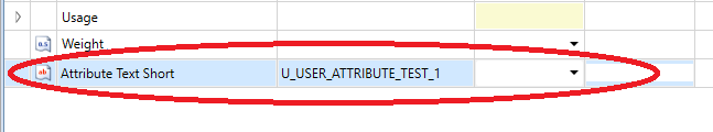
User-defined system attributes
If you have entered your own/additional attributes in the catalogue under System settings > System attributes, these are also listed in the dialogue

Referenced parts
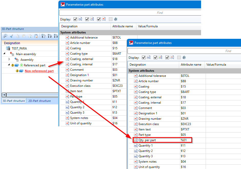
For referenced parts, the settings that are set in configuration management at System settings > Referencing > Updating are taken into account. This means that the settings defined under Synchronization of attributes are not only taken into account when updating referenced parts, but also when parameterising part attributes of referenced parts. For referenced parts, only those attributes are offered that are transferred with the part via referencing. Otherwise, the attributes that are transferred with the superordinate assembly are added.
A simple example:
The attribute number per part is to be adjusted for referenced parts only for secondary parts. The table in configuration management has been changed accordingly.
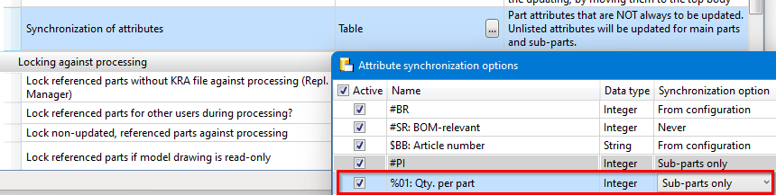
When the Parameterise part attributes function is then called for a referenced part, the attribute Qty. per part is not available, so it cannot be parameterised.
However, if the referenced part contains, for example, a non-referenced sub-part, then the attribute can be parameterised for this auxiliary part and, for example, also for the superordinate assembly.
If the referencing of the part were to be removed, then the attribute could be parameterised again.
Please note:
If a part with parameterised attributes is subsequently referenced, the parameterisation can become invalid. In this case, the respective attribute - provided you have editing rights for this attribute - is calculated and set, but the parameterisation is lost.
Example - Parameterisation of attributes
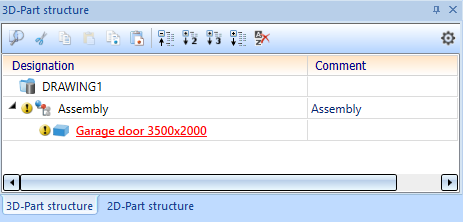
Let us assume that your company manufactures garage doors. For this purpose, there is a parameterised assembly which contains, among other things, the variables height and width, which specify the size of the garage door. However, the part created from this should not simply be called Garage door, but should contain the size.
To do this, select the part in the drawing and choose 3-D Standard > Tools > Attr... > Parameterise part attributes.
The new part number should consist of:
-
the string 'Garage door ', followed by
-
the value of the variable
width, followed by
-
the string 'x', followed by
-
the value of the variable
height.
Since it is not possible in HiCAD to append a number to a string, the numbers must be converted to strings. The function real_to_string is available for this purpose.
The formula is therefore:
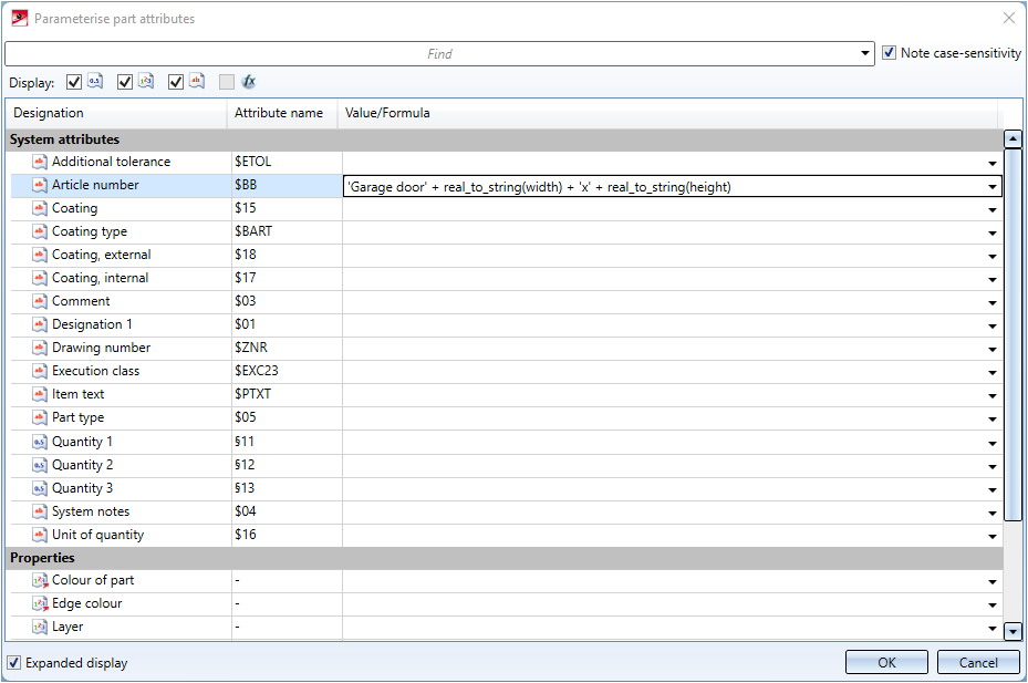
Result: