Project: HiCAD Steel Engineering
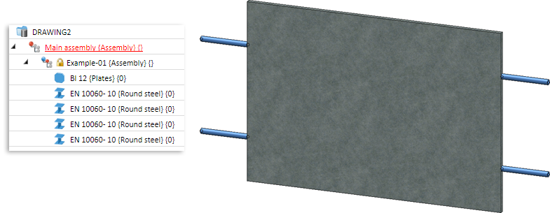
In this example a planar infill, consisting of a plate, 2 welded holders on the right ans 2 on the left are to be created as railing variants.
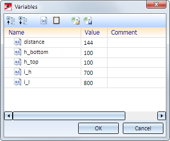
Planar infills require at least the variables i_l and i_h.
In this example, only the these two mandatory variables will be of relevance, i.e. this component can only be used for planar infills (an example for railings with rise can be found in the Example variants).
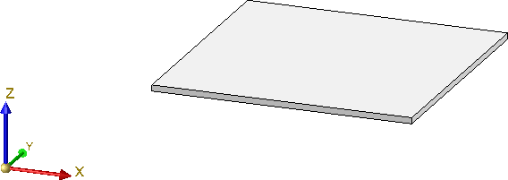
Step 1: Create and parameterize the plate
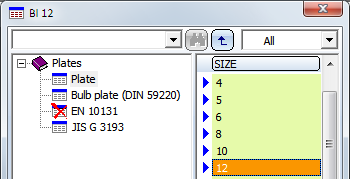
The steel plate used in our example must be derived from a sketch.
| Variable | for | Start value |
|---|---|---|
| i_h | Distance between floor and handrail | 700 |
| i_l | Distance between 2 posts | 800 |
| distance | Width of holders | 144 |
| h_top | Distance to handrail | 100 |
| h_bottom | Distance to floor | 100 |
|
h_holder |
Distance of holder from upper and lower edge of plate |
100 |
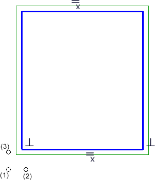
For the width and height of the plate this means:
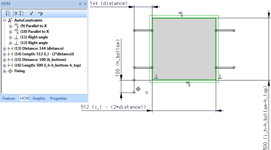
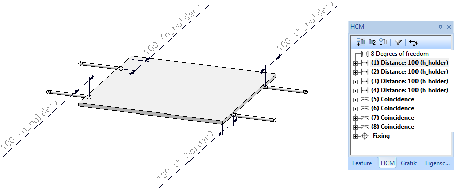
First, fix the isolated point (1) (Sketch > HCM > Fix geometry). This point represents the origin. Then, assign the variable to the sketch by defining the corresponding HCM dimensional constraints (Sketch > HCM > Smart dimensioning):
|
Dimensional constraint for |
Variable |
Start value |
|---|---|---|
|
Distance of left edge of sketch to point (1) |
distance |
144 |
|
Distance of lower plate of sketch to point (1) |
h_bottom |
100 |
|
Width of sketch |
i_l - (2*distance) |
800 for i_l |
|
Height of sketch |
i_h - h_bottom- h_top |
700 for i_h 100 for h_oben |
Step 2: Assembly and Fitting CS
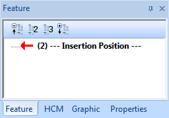
Not all assembly automatically have a Feature log. If you assign a Fitting CS to these assemblies, no corresponding Feature entry will be created. However, such an entry is mandatory for the variants. Therefore, assign a body creation feature to the assembly. To do this, right-click in the Feature window of the assembly and choose the corresponding function.
Furthermore, the function must use external references. To do this, right-click into the Feature log again and activate the External references in processings: ... option.
 to paste the variables here. The variables have now been assigned to the assembly.
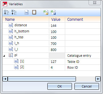
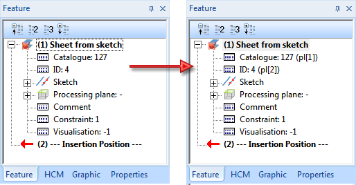
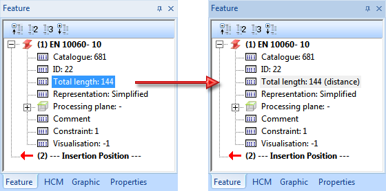
The variables pl[1] and pl[2] will be assigned to the feature of the plate:
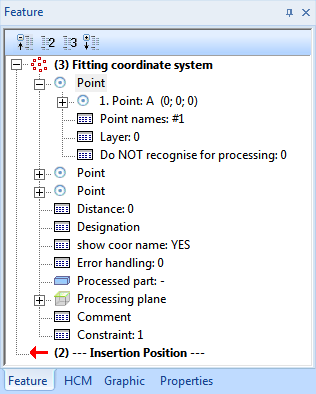
 > Define Fitting CS as follows (the assembly must be active!):
The Fitting CS will then be entered into the Feature log of the assembly (the points coincide with the isolated points you used when you created the sketch).
Step 3: Insert holders and parameterize:

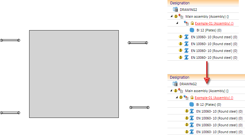
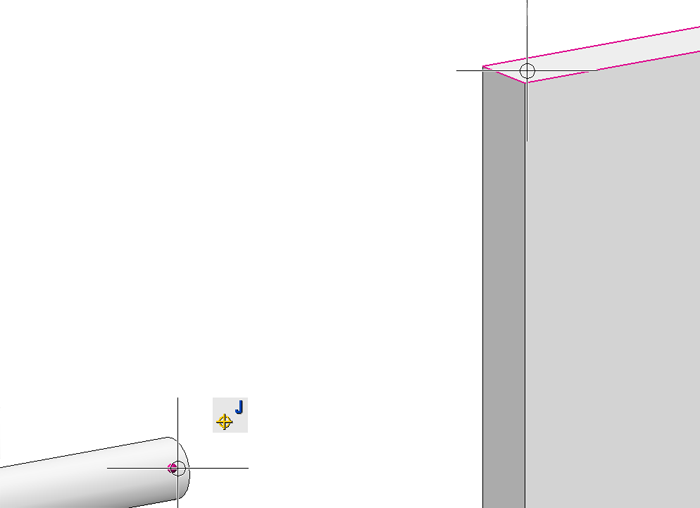
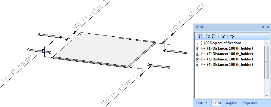
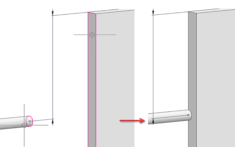
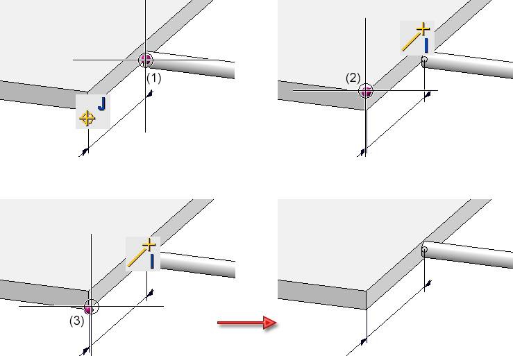
> Mid-point) is required, namely, between the end point of the holder axis and the start/end points of the plate edges.
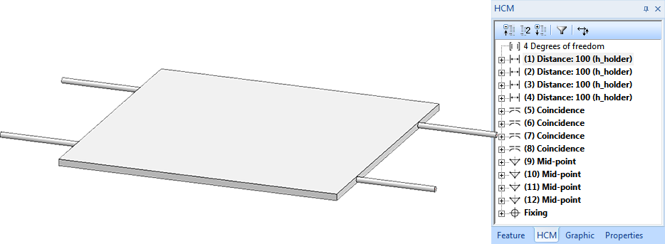
You are now done assigning all required variables and HCM constraints to the assembly.
Step 4: Save assembly as variant
To save the assembly as a variant, select the assembly and, in the Civil Engineering functions docking window, choose Steel Engineering > Stairs + Railings > Railing > Variant Editor for railings.
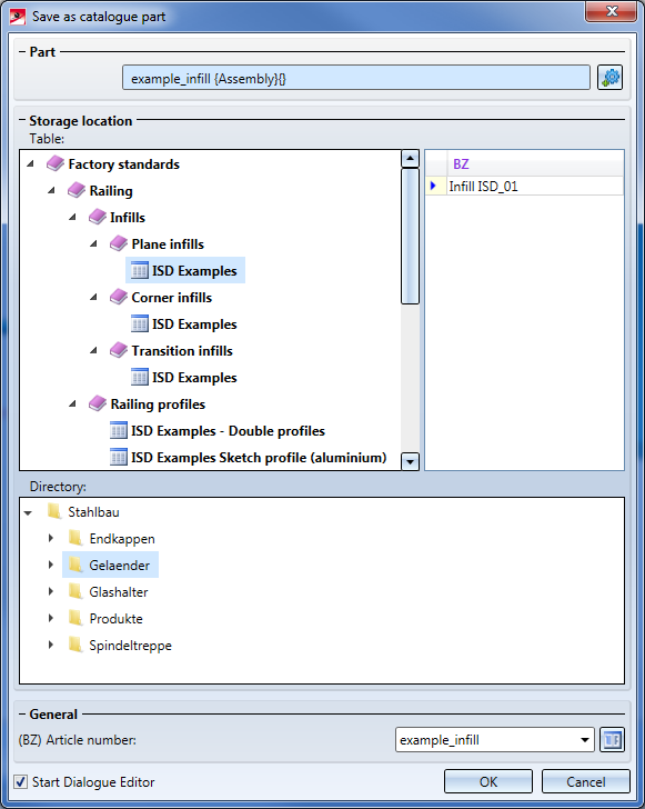
To create our customized dialogue, activate the Start Dialogue Editor checkbox and confirm with OK.
In the HiCAD folder Kataloge\Werksnormen\Stahlbau\Gelaender\EbeneFuellung the following files will be created:
The HiCAD Dialogue Editor will be started automatically and the CSV files will be loaded. The customized dialogue can now be created.
How to Create Customized Dialogues


Variant Editor for Railings • Stairs and Railings (3-D SE) • Steel Engineering Functions
|
© Copyright 1994-2020, ISD Software und Systeme GmbH |
Data protection • Terms and Conditions • Cookies • Contact • Legal notes and Disclaimer