Project: HiCAD Steel Engineering
Insert Connections - General Procedure
"Civil Engineering functions" docking window > Steel Engineering > Connections
The dialogue for the insertion of Design Variants is, more or less, similar for all functions.
General procedure:
- Select the desired connection function.
- Identify the desired beam or profile.
If you did not select a valid beam profile, HiCAD issues an appropriate error message. You can then cancel the function or repeat the selection.
If the selected connection is not possible for the identified beams or profiles, e.g. because of their position to each other, HiCAD issues an appropriate error message.
If an insertion is possible, the corresponding dialogue window is displayed.Content and number of the dialogue window depend on the function that was selected.
- Select the configuration for the insertion of the connection. Or select, if available, the insertion via a predefined DAST table. (see also Dialogue Window for Connections
- The input fields of the tab are filled with values depending on the selected configuration. If required, these values can be corrected. After making the desired selection, the input fields for the selected connections are displayed.
- If you want to create the connection with the currently set parameters, exit the dialogue window by clicking OK.
As soon as you exit the dialogue window with OK, HiCAD starts the generation of the connection and inserts it as a Design Variant. Please note that in many cases you can exclude individual components from insertion, by deactivating the Fit or Create checkbox.
Please also note the differences between the fitting of
 Please note:
- Plates, haunched plates and flange plates are combined, together with the beam to be connected, into one assembly. All other parts will belong to the beam to which the connection is made.
- For a one-sided fitting, HiCAD automatically creates an assembly containing the beam to be connected, the plate and the bolting. Assembly main part is the beam to be connected.
- For a two-sided fitting, HiCAD creates two assemblies, each of which contain the beam to be connected and the corresponding plate. The bolting is assigned to the second beam to be connected.
- Bore diameters for DAST connections are created according to DSTV testing approvals by default.
- For each generated connection, the corresponding variant is entered in the feature log in the Feature tab of the ICN.
 Important:
- If the tabs of a Design Variant dialogue window are not immediately visible after an update of HiCAD, click the Reset
 icon in the Configuration area of the window. Then, close the window and call the variant again.
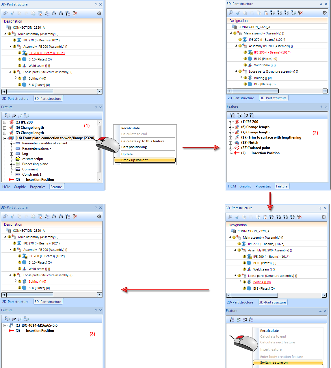
- Parts that belong to a Design Variant should not be deleted. Otherwise, there may be problems with the recalculation of the variant. If you want to delete apart belonging to a Design Variant, and then continue processing your CAD drawing, you should break up the Design Variant beforehand.
- When you break up a Design Variant, the bolting feature will be switched off automatically. This enables a continued working with the 3-D bolting functions. If you require the bolting feature again later, right-click the empty Feature window and select Switch feature on.
- When inserting Steel Engineering connections between two beams, HiCAD will check whether a superordinate assembly exists and, if so, whether it is BOM-relevant.
If no superordinate assembly exists, or if the superordinate assembly is not BOM-relevant, a BOM-relevant assembly will be created for each of the beams - structured according to DSTV guidelines. This means that the assembly will contain the corresponding beam as assembly main part and - on the same level - the components of the connection that belong to the corresponding beam.
If, however, a superordinate, BOM-relevant assembly exists, the structuring according to DSTV will not be applied. Instead, the beams and the components of the connection will be assigned to the existing assembly - without any further structuring. In this case there will be no assembly main part either. If you do not want this, you should use structure assemblies.
- Parts of a Design Variant should never be used as referenced parts that exist multiple times - neither within only one drawing nor across different drawings. As the parts will be updated via the Design Variant, problems with the recalculation can occur if one of the parts to be updated is no longer unambiguous due to the referencing.
- If a part is to be referenced, the Design Variant should be completed and then broken up. Only after the breaking up, which will make the part independent of the Design Variant, can the referencing be performed without any problems.


Connections Based on Design Variants (3-D SE) • Dialogue Windows for Connections (3-D SE)
|
© Copyright 1994-2020, ISD Software und Systeme GmbH
Version 2502 - HiCAD Steel Engineering
Date: 27/09/2020 Language: 1033
|
> Feedback on this topic
|
• • • •