Project: Report Manager
For the output of Steel Engineering bar lists, extended functions are available. These will apply to all table sheets for which the Class BarList or BarSummary has been set on the Settings sheet.
On the Bar settings sheet you can specify the cutting parameters for various semi-finished products.
On this sheet you will find a table that allows you to make settings depending of the utilized semi-finished product.
0, this row will be ignored (here: Row 4).Beneath the table you will find further setting options:
false) cuts for the rod lists are calculated in such a way that as little waste as possible will be created. If this parameter is set to true , semi-finished products the Number of which are greater than 0 will be preferred, even if there will be a larger amount of waste. H_§24 (Trimmed length). An example of the setting options for bar lists can be found in the topic Examples of BOMs: Settings for Bar Lists.
Further topics:
Please also note the settings in the Configuration Editor at Steel Engineering. There you can specify various settings for the section schema. For example, you can set here to which leg a specified angle in the section schema is to refer.

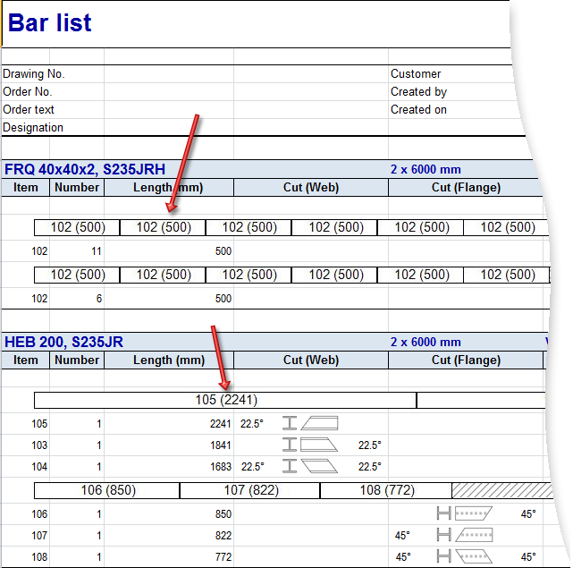
In the bar list you can, in addition to the standard placeholders, use the following placeholders for the group headers:
!BarHeader! - Header of the rod group, will be replaced with the semi-finished product !BarCount! - Will be replaced with the number of the rods!BarWaste! - Waste !CutWidth! - Cutting width !CutAddition! - Cutting allowance !DistStart! - Distance, Start !DistEnd! - Distance, End 
Template
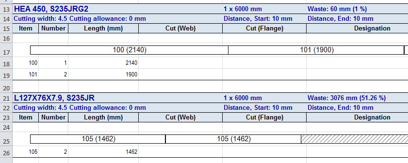
Resulting BOM
In the bar summary you can additionally use the following placeholders in the listing:
!table!BarCutWidth! - Cutting width!table!BarCutAddition! - Cutting allowance !table!BarDistStart! - Distance, Start !table!BarDistEnd! - Distance, End
Template

Resulting BOM
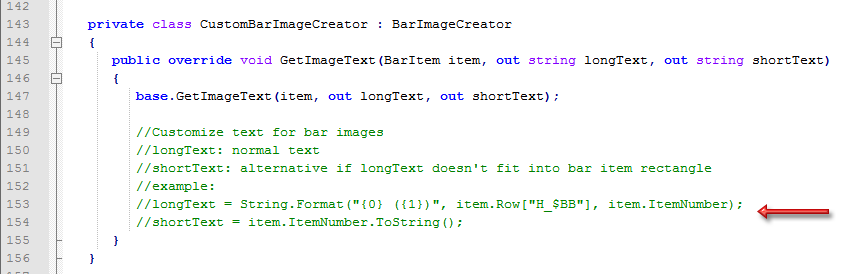
The long texts and short texts in the "images" of bar lists are now configurable. The ISD default setting is as follows:
The short text will be used if there is not enough space for the long text in an image.
These texts can be also be configured individually if desired. The configuration takes place via the script HiCAD_Stahlbau.2201.0.cs (in the HiCAD sys directory) in Line 149/150, in the form as shown in the script:
|
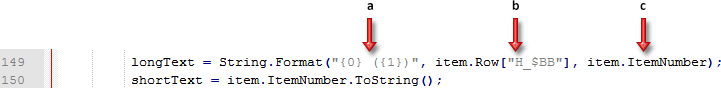
a |
Here the number of the attributes to be used for the long text is specified, and the text to be output in brackets is determined. Here: 2 attributes; the 2nd text appears in brackets |
|
b |
1st attribute; here: Article number ($BB) |
|
c |
2nd attribute; here: Item number (output in brackets) |
More examples:
|
Entry in CS file |
Meaning |
Example |
|---|---|---|
|
longText = item.ItemNumber.ToString(); shortText = item.ItemNumber.ToString(); |
Long text = Item number |
107 |
|
Short text = Item number |
107 |
|
|
longText = String.Format("{0} ({1})", item.Row["H_$BB"], item.ItemNumber); shortText = item.ItemNumber.ToString(); |
Long text = Article number (Attribute $BB) and Item number in brackets |
HEB 200 (107) |
|
Short text = Item number |
107 |
|
|
longText = String.Format("{0} ({1}) ({2})", item.Row["H_$BB"], item.Row["H_$05"], item.ItemNumber); shortText = item.ItemNumber.ToString(); |
Long text = Article number (Attribute $BB) and Part type ($05) in brackets and Item number in brackets |
HEB 200 (I - beams) (107) |
|
Short text = Item number |
107 |
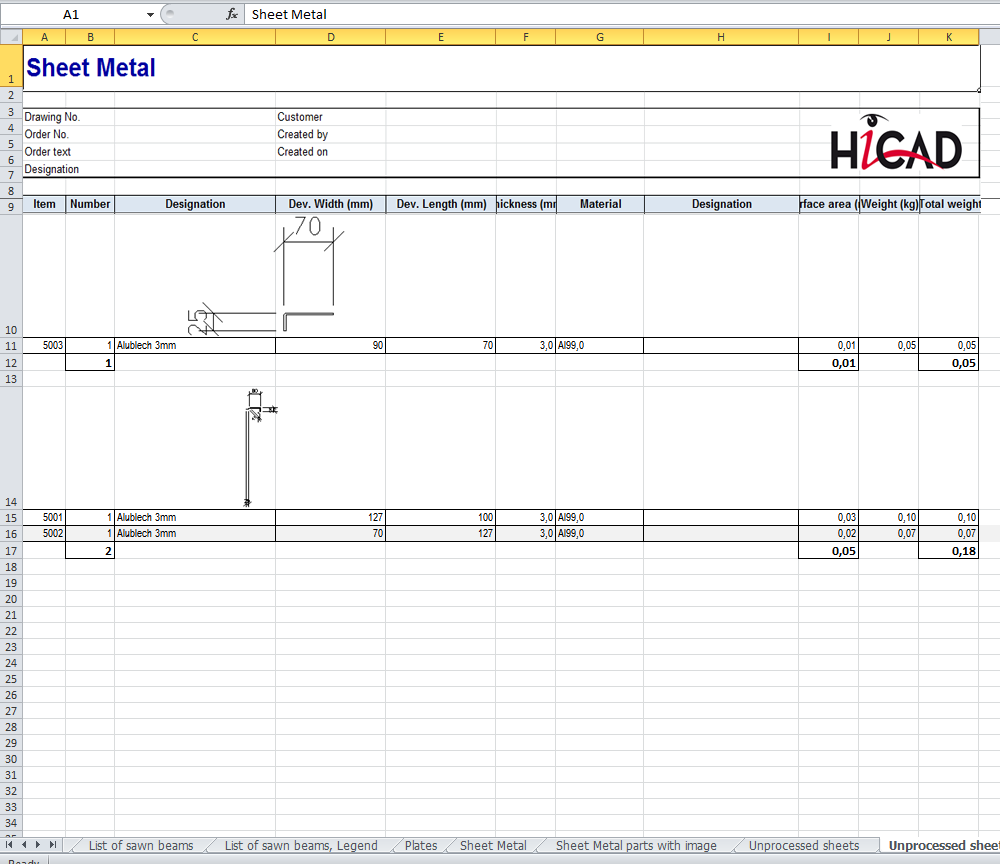
Sheet metal is now distinguished between sheets with identical cross-sections (unprocessed) and processed sheets. Unprocessed sheets with identical cross-sections are characterised by at least one bend zone, parallel front edges of the flanges (width of flange) and no further processing, e.g. subtractions, bores etc. For these sheets a drawing is not necessary, only a BOM. All other sheets count as unalike and processed.
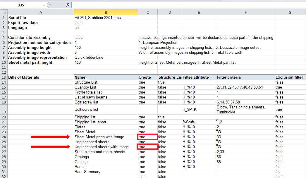
In order to differentiate between unprocessed and processed sheets in the BOM
In this case an additional spreadsheets for unprocessed sheets will be added in the Excel BOM:
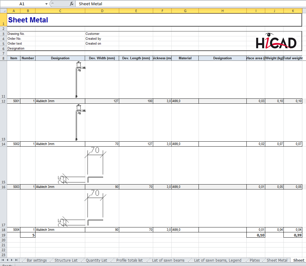
For sheet metal and unprocessed sheets you can optionally view images of the sectional view (with dimensions) in the BOM. To do so, go to the spreadsheet Settings in the HiCAD_Stahlbau.2201.0.xslx template, then to the Create column and change the value for Sheet Metal parts with image to true . The ISD default setting is false.
For unprocessed sheets with identical cross-sections only one image will be created.
The depiction with images can be found in the spreadsheets:
The generated images will be automatically scaled and, if required, rotated for the best possible display of the model drawing complete with its dimensionings.
Example:
The displayed drawing contains 5 aluminium sheets. Sheet 5001 and 5002 have different sheet depths, but they have identical cross-sections and are unprocessed. This does not apply to sheet 5000 as it has a subtraction, thus it is processed. Analogous to that, sheet 5003 is unprocessed and sheet 5004 is processed due to the subtraction.
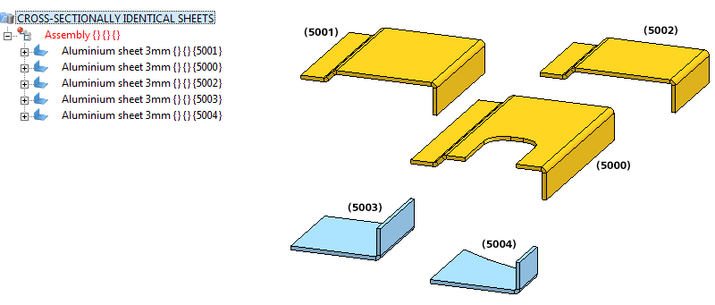
If the Special treatment for sheets with identical cross-sections checkbox is active, sheet 5001, sheet 5002 and sheet 5003 will receive special treatment in the BOM and two spreadsheets will be added.
![]() Please note:
Please note:
To be able to control the automatic page break when printing the sheet Sheet Metal parts with image, you have the option to set the maximum height (added up row height) for automatic page break on the Settings sheet of the Excel template file (e.g. HiCAD_Stahlbau.2500.0.xlsx). If a height is specified, a manual page break for grouped lists will be inserted before the group exceeding the height.
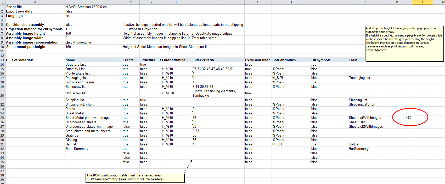
The maximum height depends on various parameters such as print settings, print areas, headers/footers.
To calculate the height you can switch, on an Excel sheet with more or less the same row heights (e.g. Structure list) and a sufficient number of filled in rows, to the Page break preview mode on the View tab. The height results from
The default value is 480 (32 rows* Row height 15).
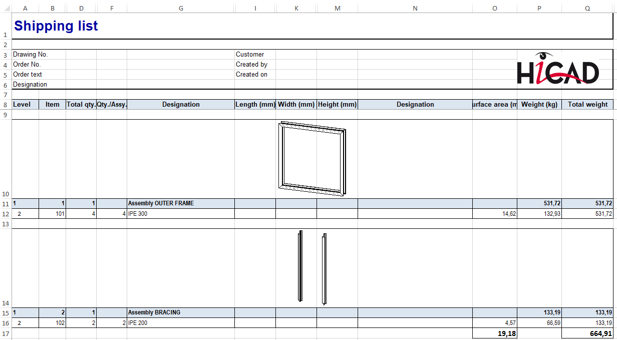
Steel Engineering BOMs allow you to define in the Excel template (HiCAD_Stahlbau.2501.0.xlsx) how BOM-relevant structure assemblies should be handled in the shipping list. For this purpose the row Ignore structure assemblies is available on the sheet Settings.
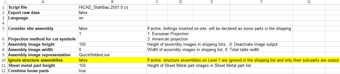
If this setting is set to true, then all structure assemblies on the first level of the part structure are ignored in the shipping list and only the sub-parts of these assemblies are taken into account.
The default setting is false.
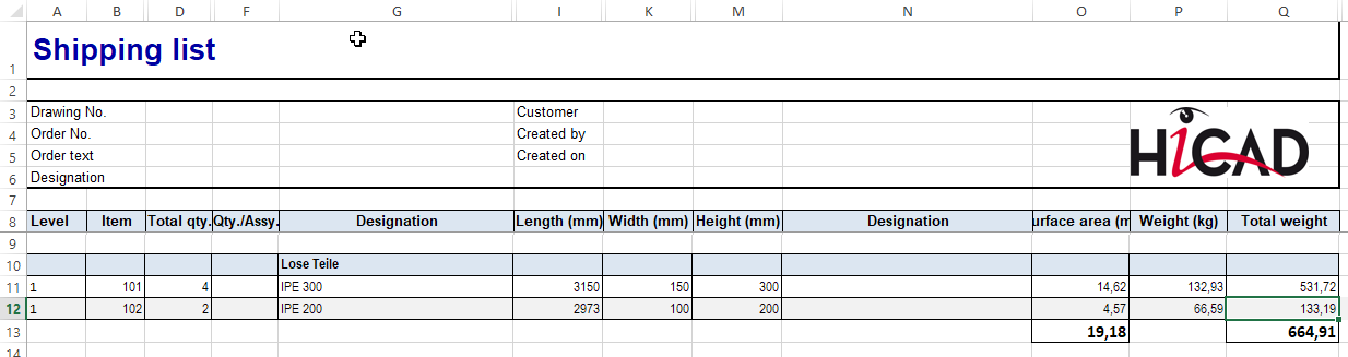
An example:
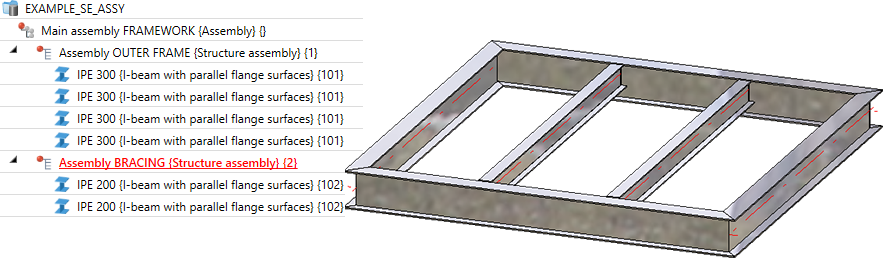
Ignore structure assemblies=true
Ignore structure assemblies=false
|
© Copyright 1994-2020, ISD Software und Systeme GmbH |
Data protection • Terms and Conditions • Cookies • Contact • Legal notes and Disclaimer