


Project: HiCAD Point Cloud
Point Cloud > Clipping box
Since point clouds are usually very large, they can only be used sensibly if so-called clipping boxes are defined for the different areas of a point cloud. By defining so-called clipping boxes, unneeded parts of the point cloud can be temporarily cut away, so that the remaining area of the point cloud can be better measured or edited. For example, only the back wall or the floor of a building can be displayed and edited.
The following functions are available:
|
|
|
|
|
|
|
|
|
|
|
The point cloud used in the following illustrations is an example provided by VHV-Anlagenbau GmbH, Hörstel.

Point cloud > Clipping box > Create clip...
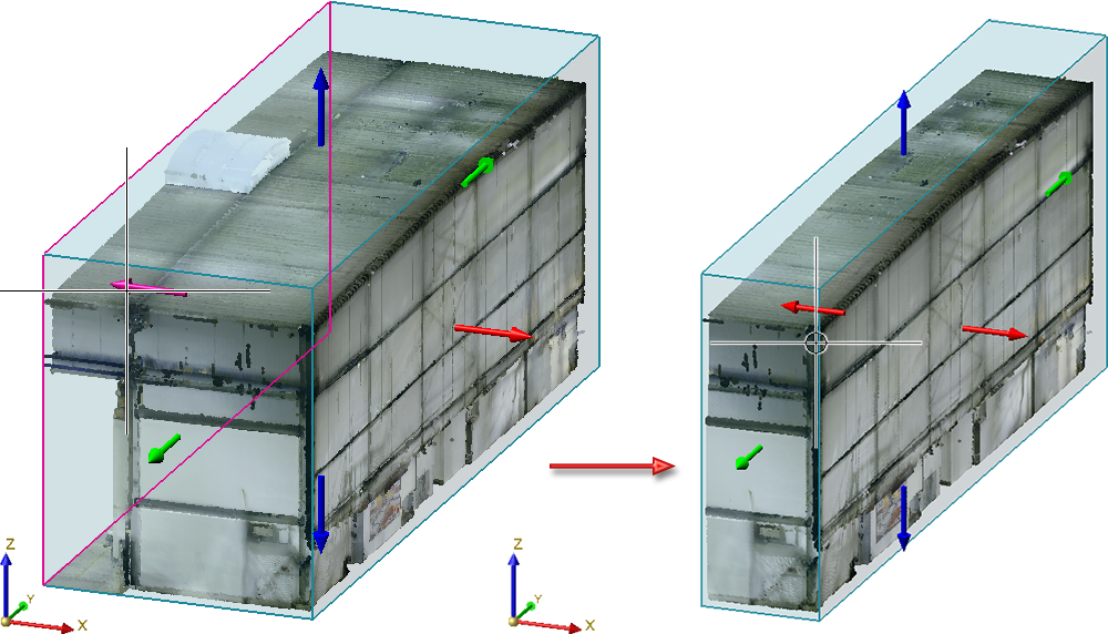
Use this function to create a new clipping box. HiCAD creates an bounding box around the point cloud. This is the smallest axially parallel cuboid that completely encloses the point cloud. At the same time, direction arrows are displayed in positive and negative direction of the X-, Y- and Z-axis. By clicking on an arrow with the cursor, you can reduce or enlarge the box by dragging the cursor dynamically in the selected direction. The clipping box is defined by specifying a point. This can be done by dropping the cursor, by taking over a snap point displayed by the autopilot or with any other point option, e.g. the point option (PW) Point from point cloud.
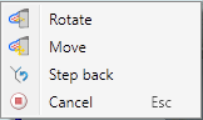
You can right-click to open a context menu with further functions can be activated. With this function, the current clipping box can be rotated or moved.
If you choose Rotate, the clipping box can be rotated around an axis by selecting the rotation circle of the respective axis with the cursor and then rotating it dynamically with the cursor.
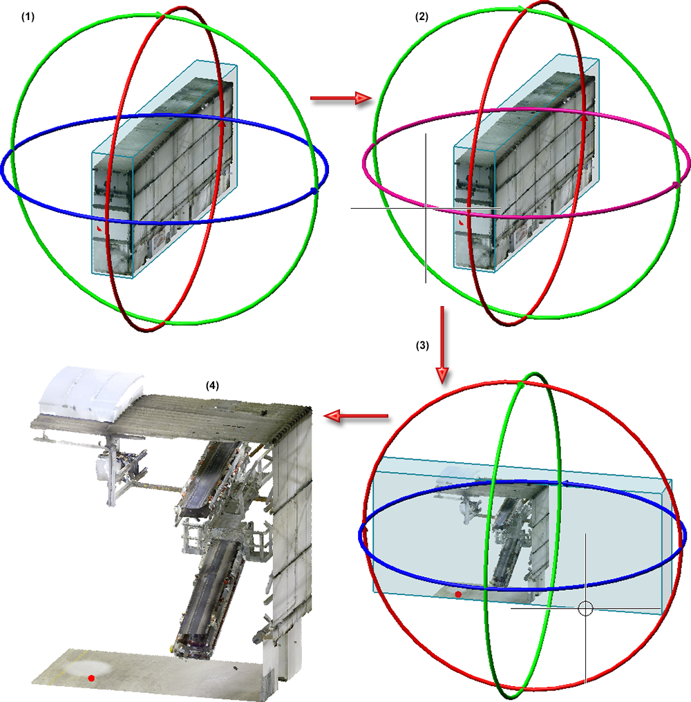
(1) Current clipping box, (2) Selection of Z-axis as rotation axis, (3) Rotated clipping box, (4) Cropped point cloud
If you choose Move, the corner points of the clipping box are visualized in the drawing. You then select the point to be moved and determine the new position with the cursor.
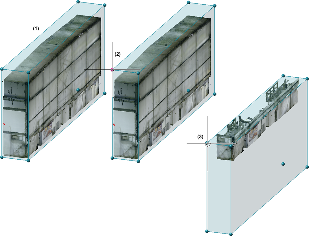
(1) Current clipping box with visualized corner points, (2) Selection of a point, (3) Moved clipping box
The preview of the clipped point cloud is always updated immediately in the model drawing. The current display is adopted by pressing the middle mouse button (MMB).
You can also define several clipping boxes. If a clipping box already exists when the function is called, it is visualised in the drawing . You can then simply define further boxes.
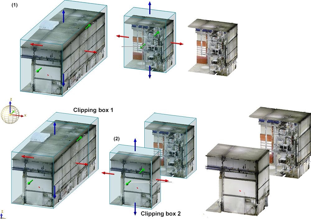
(1) Definition of the first clipping box, (2) Definition of a second clipping box
Tipp:
In practice, it may make more sense to create the clipping boxes in the standard views (front view, side view, top view) rather than in the perspective view.
Point cloud > Clipping box > Edit clip...
With this function, clipping boxes can be edited subsequently. After calling up the function, the defined clipping boxes are displayed and you can edit the boxes analogously to the definition of clipping boxes, i.e. scale, rotate or move them. Here, too, the boxes can be transferred using the middle mouse button.
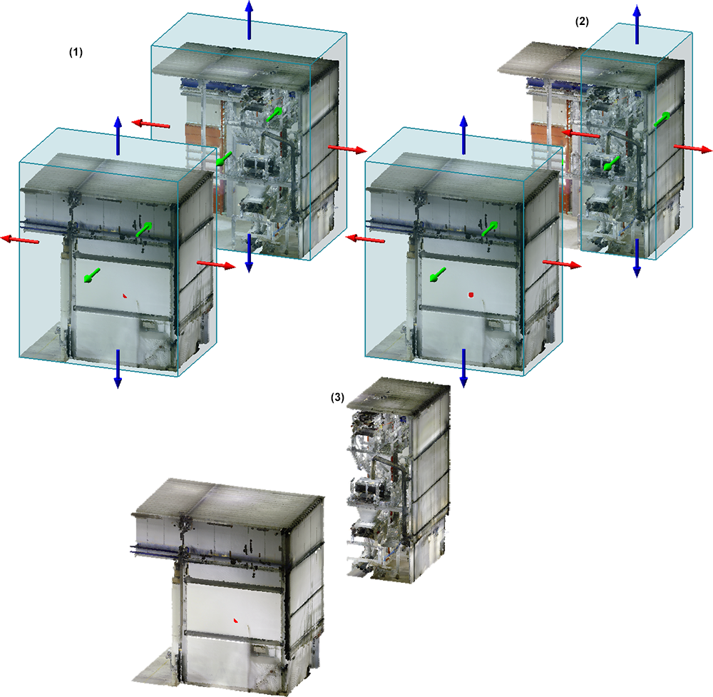
(1) Defined clipping box, (2) Editing of the upper clipping box, (3) Result
Point cloud > Clipping box > Delete clip...
Use this function to delete clipping boxes. Select the clipping boxes to be deleted one after the other and end the selection with the middle mouse button.
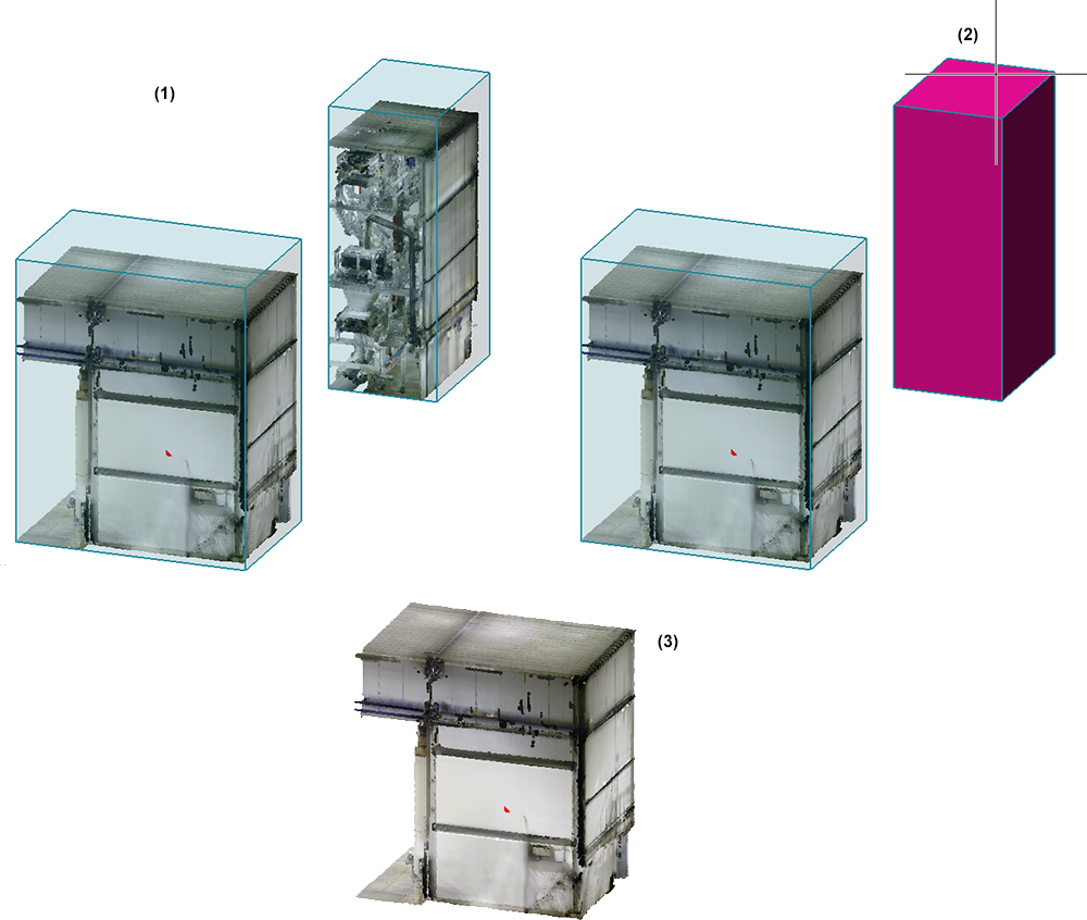
(1) Defined clipping box, (2) Deleting of the upper clipping box, (3) Result
Point cloud > Clipping box > Toggle clip...
This function allows clippings to be inverted, i.e. the display mode will be switched. By default, all points within the boxes are displayed. Toggle clipping reverses this state so that all points outside boxes will be displayed.
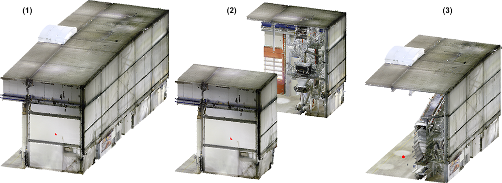
(1) Original point cloud, (2) Point cloud trimmed by two clipping boxes, (3) Point cloud after toggling the clippings

Procedure • Point Cloud Functions • Point Cloud: Examples
|
© Copyright 1994-2020, ISD Software und Systeme GmbH |
Data protection • Terms and Conditions • Cookies • Contact • Legal notes and Disclaimer