 > Angle...
Project: HiCAD Parametrics
3-D Standard > HCM > Distance > Angle...
You find the  Angle function in the pull-down menu of the Distance function in the HCM function group of the 3-D Standard tab.
Angle constraints can be set between two geometries.
If an angle constraint is created, the existing angle is always used as a positive value. If you want to change the direction of the angle, you can change the sign. If you only change the value of the angle, but not the sign, the dimension direction of the angle constraint remains unchanged.
 Instead of specifying an angle of 0 or 180 degrees, you should rather use the
  Parallelism constraint, since the calculation effort is considerably lower there.
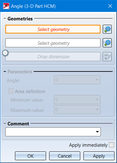
First identify the two Geometries.
Activate the Drop dimension field to drop the generated dimension. In this case, select the point to which the dimension is to be dropped.
You can then specify the angle constraint more precisely in the Parameters area: After identifying the two geometries, the current distance is entered in the Angle field. You can also enter a different distance here. Or you can assign an Area definition by activating the same-named check box. In this case you must also fill in the Minimum value and Maximum value fields. The value Angle must lie between these two values; otherwise, a corresponding error message is displayed. If an area definition is given, it takes precedence over the angle constraint - the latter can therefore be ignored by the HCM as long as the selected area is kept.
The other control elements are described in the topic Dimensional and Positional Constraints.
With the context menu, angle constraints can be set to an element of the coordinate system, just as to geometry elements of the drawing. You open the context menu by clicking the right mouse button after identifying the first geometry.
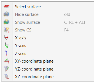
Via the functions of the context menu you can then determine the angle constraint between the selected geometry element and
of the coordinate system.
Alternatively, by selecting the Show CS function or pressing the F4 key, you can display the coordinate system of the selected body and then use one of these axes for the constraint.


|
© Copyright 1994-2020, ISD Software und Systeme GmbH |
Data protection • Terms and Conditions • Cookies • Contact • Legal notes and Disclaimer