 Direct distance between two parts as well as Distance, parallel to X-/Y-/Z- axis can be found in the HCM function group of the 3-D Standard tab.
Project: HiCAD Parametrics
3-D Standard > HCM > Distance
The functions Direct distance between two parts as well as Distance, parallel to X-/Y-/Z- axis can be found in the HCM function group of the 3-D Standard tab.
With this function you assign a distance constraint. These are always true three-dimensional distances, i.e. the two-dimensional distance is not measured in the view.
The Assembly HCM always regards geometries as unlimited. For example, the distance of a point to a straight edge is measured in such a way that the perpendicular of the point is dropped onto the straight edge on which the line lies. This distance can be different from the distance of the point from the edge, if this perpendicular is not on the line. However, if you want to use just this distance, you must assign distance constraints to boundary points or edges.
Distances to planes may also imply parallelism, for example, the distance of the surface to lines, cylinders or other surfaces. In contrast, this does not happen automatically for distances to lines, so that, for example, the distance between two skewed lines can be measured.
You can also define a distance with the value 0, but it is better to assign an Coincidence constraint instead. This can be processed more quickly and solutions are easier to find for complex systems.
If at least one of the selected geometries is a surface, the sign of the distance value controls the orientation of the distance condition. The first selected surface serves as a reference surface. If the distance value is positive, the distance away from the body to which the reference surface belongs is measured. If the value is negative, the distance "into the body" is measured. If you change the sign of the value, the orientation of the dimensional constraint changes accordingly. If you change the value, but leave the sign unchanged, the orientation remains unchanged.
If none of the geometries is a surface, the value is always positive. Negative algebraic signs are treated as positive signs, but also result in a warning being displayed.

3-D Standard > HCM
Use the distance constraints
 Parallel to X-axis
 Parallel to Y-axis
 Parallel to Z-axis
to specify a distance value relative to the corresponding coordinate system axis of the active HCM assembly.
The constraint can only be assigned between 2 points here.
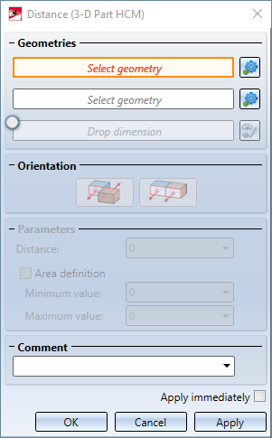
First identify the two Geometries. You can select points, lines, edges, coordinate axes or surfaces.
Activate the Drop dimension field to drop the generated dimension. In this case, select the point to which the dimension is to be dropped.
You can then specify the distance constraint more precisely in the Parameters area: After identifying the two geometries, the current distance is entered in the Distance field. You can also enter a different distance here. Or you can assign an Area definition by activating the same-named check box. In this case you must also fill in the Minimum value and Maximum value fields. The value Distance must lie between these two values; otherwise, a corresponding error message is displayed. If an area definition is given, it takes precedence over the distance constraint - the latter can therefore be ignored by the HCM as long as the selected area is kept.
The other control elements are described in the topic Dimensional and Positional Constraints.
With the context menu, distance constraints can be set to an element of the coordinate system, just as to geometry elements of the drawing. You open the context menu by clicking the right mouse button after identifying the first geometry.
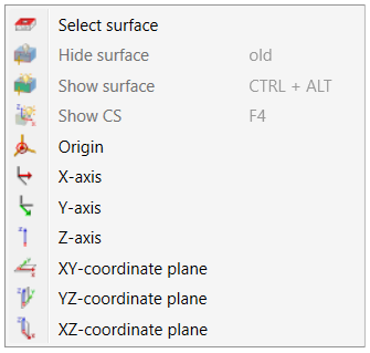
Via the functions of the context menu you can then determine the distance constraint between the selected geometry element and
of the coordinate system.

|
© Copyright 1994-2020, ISD Software und Systeme GmbH |
Data protection • Terms and Conditions • Cookies • Contact • Legal notes and Disclaimer