3-D Sketches: General Notes
Some construction elements in HiCAD use 3-D sketches, e.g. extruded solids and holes. A sketch always includes a sketch plane and hence a sketch coordinate system. The 3-D sketch/the resulting processing is anchored to this coordinate system.
If you use the feature log to change objects based on sketches by processing the sketch, the position of the sketch coordinate system determines whether the processing executed with the 3-D sketch is translated or retains its position.
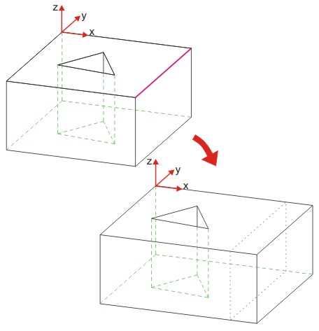
Example 1: Move edge with R 30 00
The example shows an extruded solid derived from a sketch. In the feature log, the Process sketch function was activated and then the marked edge moved by the value 30 in the direction of the x-axis using the Move, points function. The modified sketch was then transferred to the feature log.
The next example uses the same extruded solid. Again, the Process sketch function was activated in the feature and then the marked edge moved by the value 30 in the direction of the x-axis using the Move, points function log. Here, however, unlike the preceding example, the sketch CS was rotated 180° before edge selection using thePlanefunctions /Transform/Move/Rotate sketch functions.
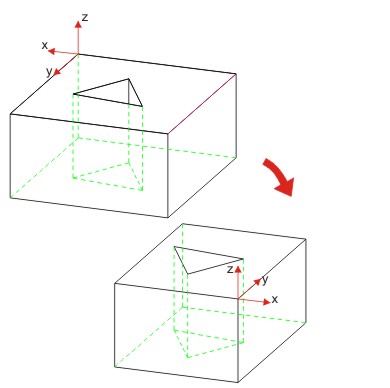
Example 2: Rotate Sketch CS 180°, Move edge with R 30 00 -> Part is rotated
If the changed sketch is applied, it causes the extruded solid to be moved and rotated. The sketch itself is only moved if you click YES to confirm the message shown (see Feature Configuration).
Note that this message is only displayed if the setting Issue message when moving sketch for extruded part is activated in the feature configuration.

