Project: HiCAD Element installation
This example demonstrates the setting up of template drawings for self-made variants for the element installation. It follows the same three steps as the technical description of the setting up of template drawings:
This example assumes that you have already created a separate variant for the element installation. For a description of the steps required for this and examples of how to do this, see Customer-specific Installation Elements .
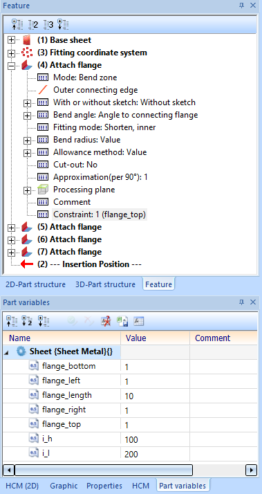
We are working here with the (fictitious) variant ISD-17, which is based on a simple, rectangular sheet metal. It is stored in the catalogue folder in a folder Werksnormen\Elementverlegung\Example\ISD-17. Besides the variables i_h and i_l, which the element relocation uses to configure the size of the elements, the variables flange_top, flange_bottom, flange_left and flange_right are also available. These can contain the values 0 or 1 and control whether a flange should be present on one side of the sheet (1) or not (0).

For the different sub-types of the variant, different drawing templates can be used. For example, a simple top view is sufficient for the version without flanges. If there is a single flange, it is sufficient to add a front or side view, while for more than one flange an axonometric view may be necessary to better estimate the position of the flanges.
In this example, we will create only four templates: One for the simple case from a simple top view; one with an additional front view in the case of a flange at the top edge; similarly, a template with a side view for flanges at the left side; and a template with top, front, side and axiometric views in the case of a flap at the left and one at the top edge. The other cases are left out here, but they would be similar.
As a starting project, we create a new element installation with our element in which the variations to be considered occur:
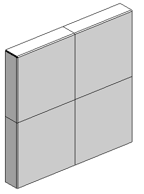
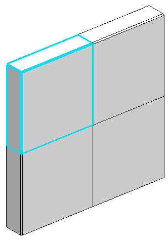
Let's start with the top left element.
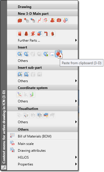
It must be copied into a new model drawing. By right clicking on the part in the ICN and choosing Others > Copy to clipboard we copy the part to the HiCAD clipboard.
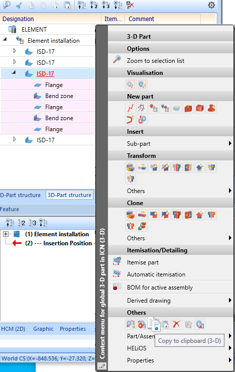
in.
Then we create a new model drawing via Drawing > New. Here we create a main assembly via 3-D Standard > New > Assy.  > Main assembly. Then we insert the copied part by right-clicking and choosing Insert > Paste from clipboard.
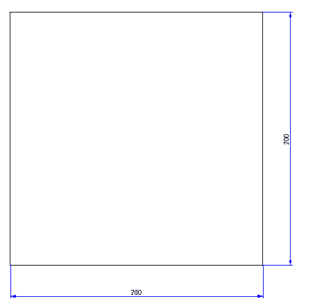
Then we switch to Sheet 1 and create 4 views by selecting Views > New > 4 Standard views, and assign some dimensions via 3-D Dimensioning+Text > Individual dimension > Variable:
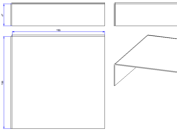
Then we save the model drawing. The model drawing must be saved in the catalogue below Werksnormen (Factory standards); since the variant itself is also saved there, the folder Werksnormen\Elementverlegung\Example\ISD-17 is a good choice. We call this drawing TEMPLATE-DRW_TOP_LEFT.SZA.
This drawing can now be closed.
Similarly, we create the files TEMPLATE_DRW_FLANGE_TOP.SZA for the element with only the flange on top, TEMPLATE_DRW_FLANGE_LEFT.SZA for the element with only the flange on the left and TEMPLATE_DRW_NO_FLANGES.SZA for the element without flanges:
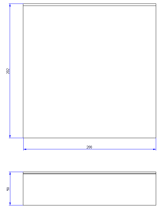
TEMPLATE_DRW_FLANGE_TOP.SZA
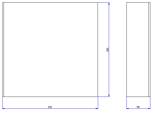
TEMPLATE_DRW_FLANGE_LEFT.SZA
TEMPLATE_DRW_NO_FLANGES.SZA
In order to assign the different drawing templates to the different sub-types of the variant, a text file is required that specifies which template file is to be used for which part variables. This is divided into blocks, where the name of the template file is always given first and then the variables that must be given so that this template can be used for an element. The first block that applies to an element is applied without considering subsequent blocks. This text file must also be located in the catalogue directory below Werksnormen. Since the other files for this variant are already located in the folder Werksnormen\Elementverlegung\Example\ISD-17, it is advisable to create this text file there as well. You can also create this text file under the file name ISD-17.txt. This file can be edited, for example, e.g. with the editor notepad.exe supplied with Windows or another text editor.
The content of this file must be as follows for this example:
Elementverlegung\Example\ISD-17\TEMPLATE_DRW_FLANGE_TOP_LEFT.SZA
flange_top = 1
flange_left = 1
Elementverlegung\Example\ISD-17\TEMPLATE_DRW_FLANGE_TOP.SZA
flange_top = 1
Elementverlegung\Example\ISD-17\TEMPLATE_DRW_FLANGE_LEFT.SZA
flange_left = 1
Elementverlegung\Example\ISD-17\TEMPLATE_DRW_NO_FLANGES.SZA
The first block specifies that TEMPLATE_DRW_FLANGE_TOP_LEFT.SZA should be used if both flange_top and left_flange have the value 1.
TEMPLATE_DRW_FLANGE_TOP.SZA is used when flange_top has the value 1. Since elements with tabs left and above have already been treated by the first block and are not processed any further, we do not need to list a flange_left = 0 here. The same principle applies to TEMPLATE_DRW_FLANGE_LEFT.SZA.
The block for TEMPLATE_DRW_NO_FLANGES.SZA has no conditions listed. So it is always used - if the respective element was not just handled by a previous block.
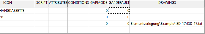
Finally we have to inform HiCAD that these templates should be used for this variant. For this we start the Catalogue Editor and navigate to the catalogue entry of our variant. Our example variant ISD-17 can be found at Factory standards > Installation planning - Parts + Processings > Element installation > Installation Elements > ISD Example. In the table we will find the column DRAWINGS. Here we enter the path to the text file created in Step 2 - again relative to the Factory standards folder:
Now we can use the Template drawing function to generate drawings for an element installation with these elements.

Element Installation Template Drawings
|
© Copyright 1994-2020, ISD Software und Systeme GmbH |
Data protection • Terms and Conditions • Cookies • Contact • Legal notes and Disclaimer