
Project: HiCAD Element installation
You can create own parts for a later use in sub-structures.
The most common parts for this purpose are profiles, but you can also create any other part variant, in particular entire assemblies, to be used in sub-structures, as long as they have been parameterized via their length.
To do this, the following criteria must be met:
You can also parameterize other part variables. These can then be configured in the Part variables area of the Sub-structure dialogue window.
In the following example, a U-profile for a use in sub-structures is to be created, with configurable width, height and thickness. The creation of the profile takes place in 5 steps:
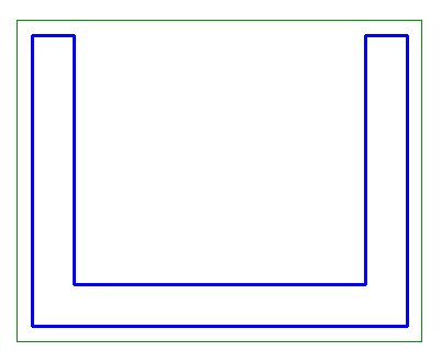
First, draw a rough sketch:
Parameterize the sketch and define suitable positional constrains:
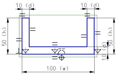
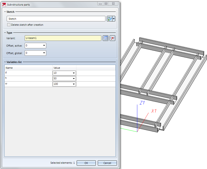
The variable d stands for the thickness of the profile, h for the height and w for the width. In the mid point of the lower line there is a point which is fixed and in a Coincidence constraint with the mid point of the line. In his way it is ensured that the sketch will always stay aligned to this point even in case of value changes.
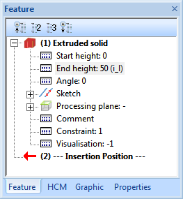
Convert the sketch into a 3-D part by choosing 3-D Standard > New > Extruded solid.
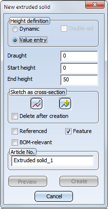
Since an utilisation of part variables is not possible in this dialogue window, enter an (arbitrary) value for the height here, and change it later, in the Feature of the extruded part, to length:
Assign a Fitting CS to this part: Choose Drawing > Others > World CS  > Define Fitting CS. First, specify the origin of the Fitting CS; place it into the mid point of the lower line.
Then, define a point on the X-axis; select the mid point of the lower edge of the part on the other side as origin.
Finally, you need to specify a point on the Y-axis: Select the point on the left corner on the front side of the part.
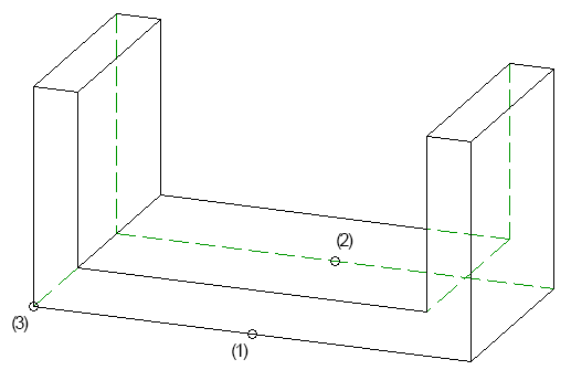
(1) Origin, (2) Point on X-axis, (3) Point on Y-axis
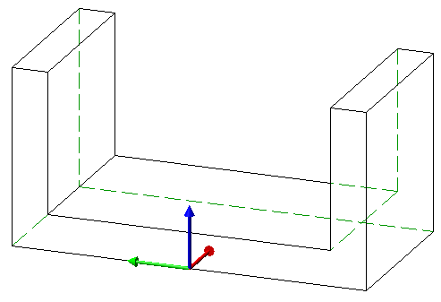
Result (the Fitting CS will only be displayed if you select the Feature Fitting CS).
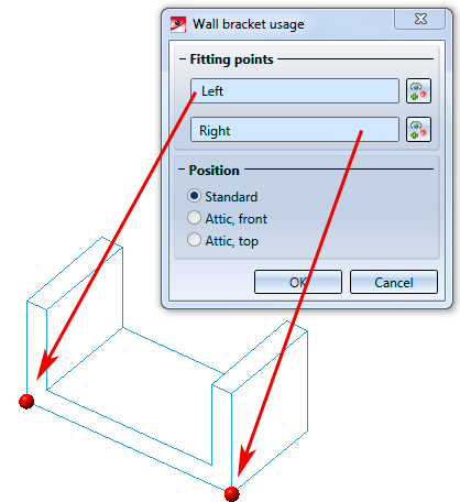
To enable the use of the new profile with wall holders, wall bracket usage data needs to be assigned to the profile. To do this, choose Element installation > Wall bracket usage in the Civil Engineering functions docking window. The following dialogue window will be displayed:
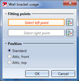
Form wall brackets which are laterally mounted to the new profile, HiCAD needs to know the width of the profile, or the lateral offset of the wall brackets from the profile axis. For this purpose, HiCAD will ask for Fitting points. "Left" and "right" refers to the profile in the top view - "left" is located on the Y-axis in the positive area, right in the corresponding negative area.
The profile is built as a normal profile, and not as a part of an attic construction, therefore, the setting for the Position can remain on Standard.
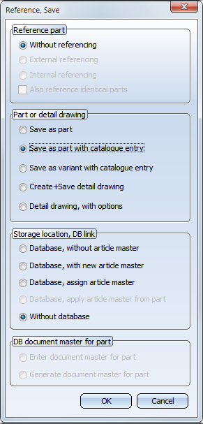
Save the part via Drawing > Save / Reference > Reference part, Save, Detail drawing. In the dialogue window, set the options as shown below:
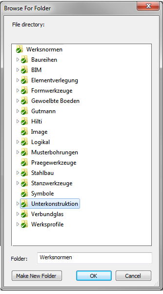
Choose the Unterkonstruktion (=Sub-structure) folder as target folder:
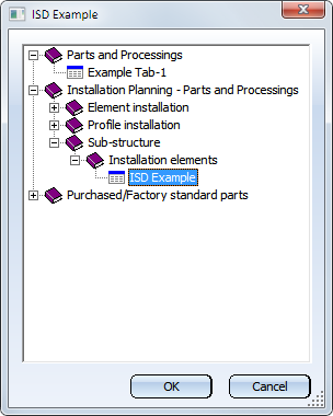
Choose the table Installation planning - Parts and Processings > Sub-structure > Installation Elements > ISD Example for the new catalogue entry.
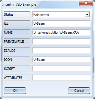
Enter the data for the new profile - BZ contains the designation of the profile, and is initialized with the name of the part by default. The other fields are initialized with meaningful values which can be applied as such. Their meanings are as follows:
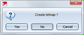
HiCAD will ask you whether a preview graphic for this profile is to be created. As this will not be necessary here, click No.
The new profile can now be used in sub-structures:

|
© Copyright 1994-2020, ISD Software und Systeme GmbH |
Data protection • Terms and Conditions • Cookies • Contact • Legal notes and Disclaimer