Project: HiCAD Element installation
In the following, the creation of a customer-specific dialogue with the HiCAD GUI Creator will be explained using the example of a customer-specific installation element.
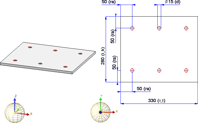
Here we use the drilled plate as an example:
Before we create a dialog, we will extend the example as follows:
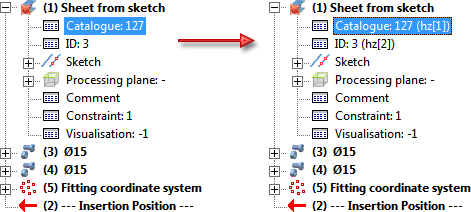
In the example, a specific semi-finished product has been used so far, namely a sheet from the table Plates (table ID 127) with a thickness of 10 (Row ID 3). However, we would like to be able to select the semi-finished product flexibly during installation and therefore we define a corresponding variable of type List. To do this, right-click on the sheet in the ICN and select Properties > Part variables. Then select the function Add variable  and insert a variable, e.g. hz, of the type List. Now right-click on the line with the new variable and select Add new variable from the context menu. You do not need to specify the name here; it is determined automatically. Select Number as the variable type and the table ID as the initial value, e.g. 127 for the table Semi-finished products > Plates > Plate. After exiting the dialogue with OK, the sub-variable is created, whereby a consecutive number in square brackets is automatically used as the name, e.g. [1]. Proceed likewise to create the variable for the Row ID.
In the feature of the plate you then enter the variables hz[1] and hz[2] for Catalog and ID:
It shall be possible to install the panel with or without holes. This is to be solved in our example dialogue with radio buttons. For these RadioButtons we still need a variable, e.g. b. For this we define a number variable and set the initial value to 0. The default setting in the user dialogue should later be No, i.e. plate without holes. Therefore we also set the initial value of the diameter (variable d) to 0.
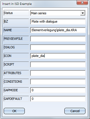
Now, save the changed plate in the Installation elements catalogue:
You can now start with the design of your GUI.
Start the HiCAD GUI Creator by calling the file
HiCADGUICreatorApp.exe
from the HiCAD EXE directory.
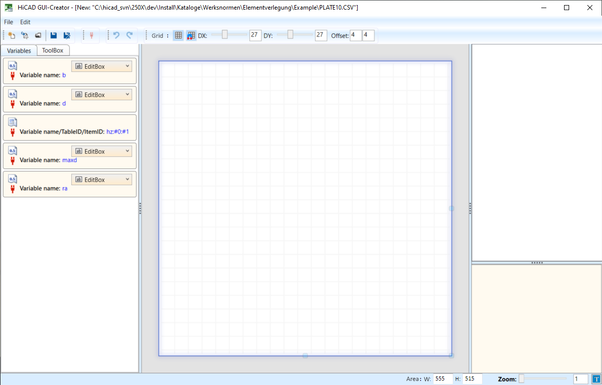
After calling the editor, the HiCAD GUI Creator dialogue window is displayed. The New function creates a new dialogue window. The previously saved file plate_dia.csv is required for this.
The Variables tab contains all variables assigned to the plate.
What should the dialogue window look like?
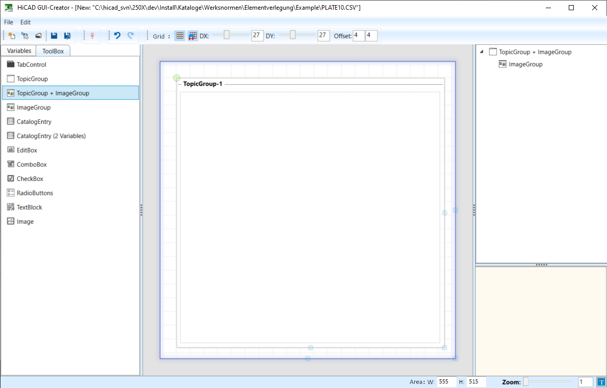
That means we will need a toolbox object of the type TopicGroup + ImageGroup.
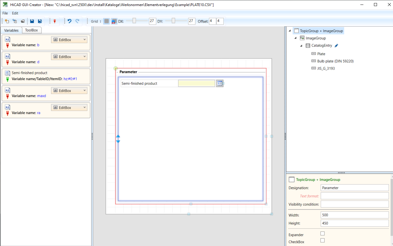
Step 1: Insert the Toolbox object TopicGroup + ImageGroup
Just drag the required object from the Toolbox into the dialogue.
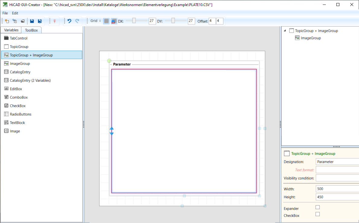
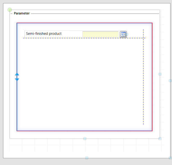
Then mark the TopicGroup (marked red) and edit the parameters as desired, e.g.:
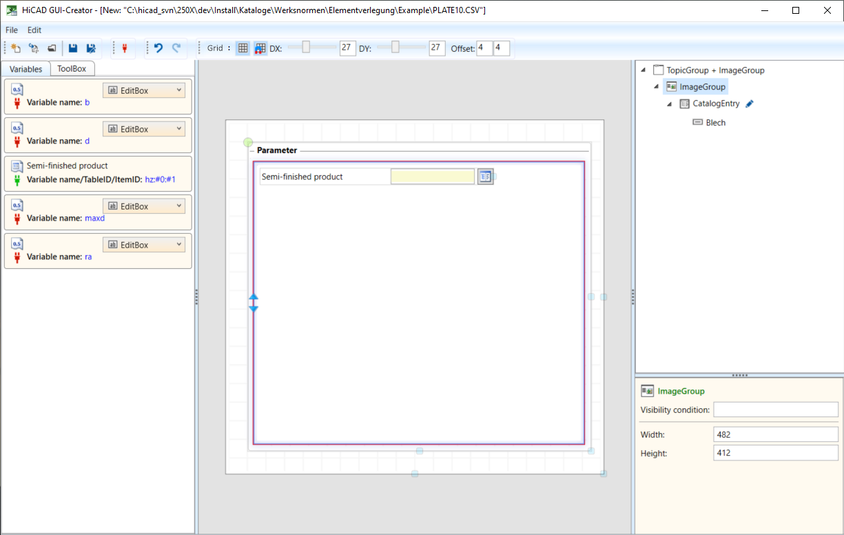
As already mentioned above, the ImageGroup should contain the fields:
Step 2: Select semi-finished product
Select the ImageGroup and activate the Variables tab. Then first drag the variable hz into the ImageGroup. An object of type CatalogEntry is inserted automatically.
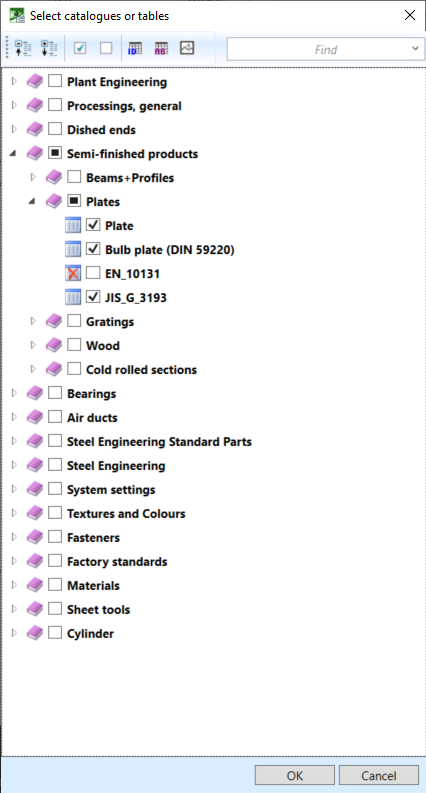
In the tree structure, click on the  symbol to select the desired catalogues:
Step 3: RadioButtons for bores
The query whether the plate should be with or without holes is to be realized by radio buttons. For this purpose we select the object type RadioButtons for the Variable b and then drag the variable into the ImageGroup.
The variables are automatically aligned "tabularly".
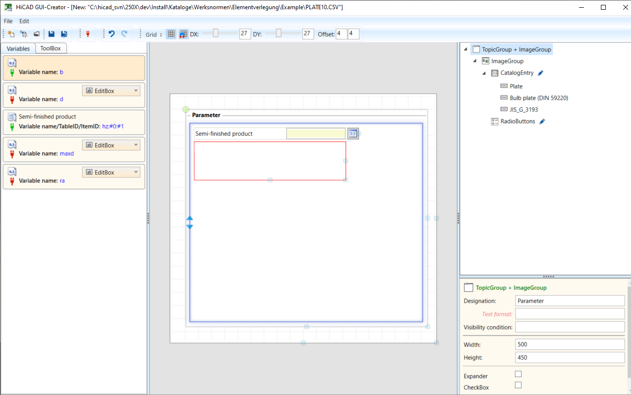
Here, too, edit the parameters, e.g.:
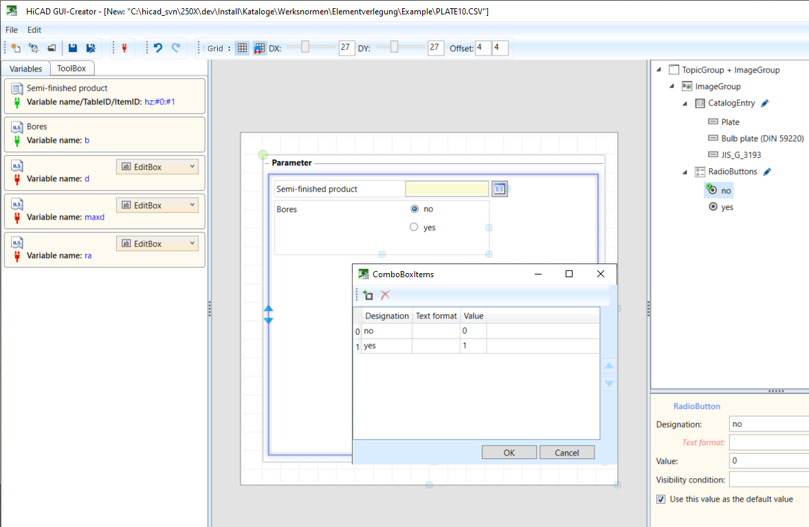
Select no as the default setting.
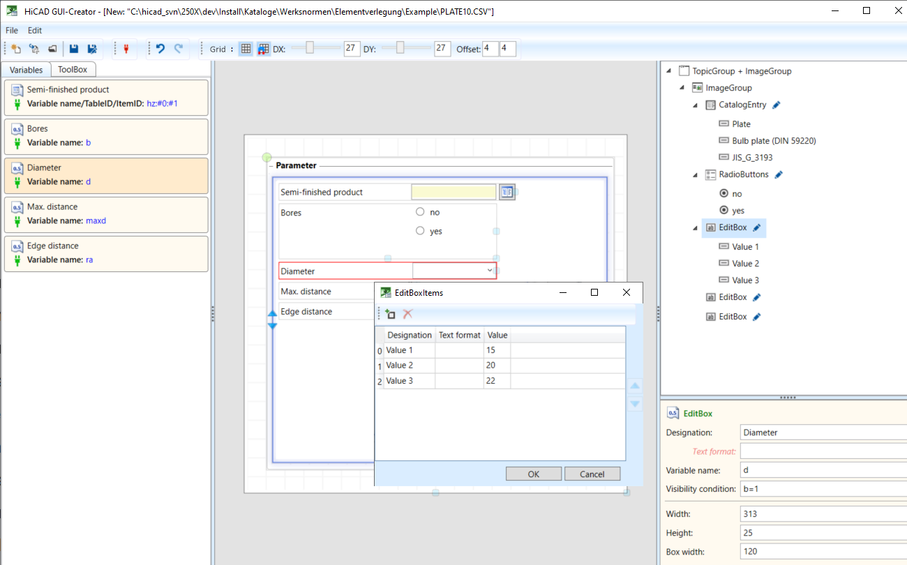
Step 4: Insert further input fields
Drag the variables d, max, and ra as EditBoxes into the ImageGroup, e.g.:
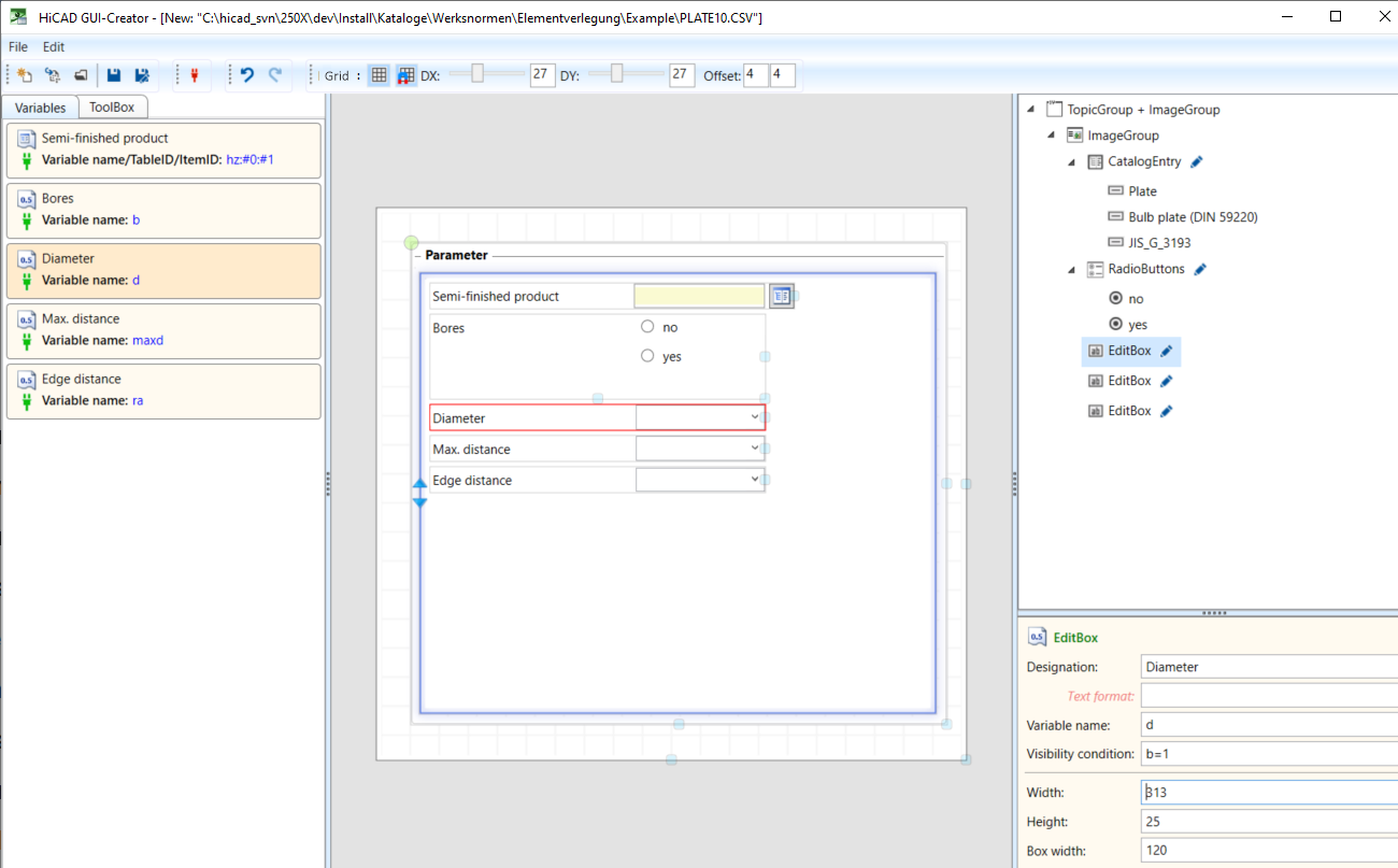
Here, too, enter initial values for the variables, e.g. for the Diameter:
Since all three input fields should only be visible if the Bores: yes option is active, a visibility condition must be specified for all three variables, in this case b=1.
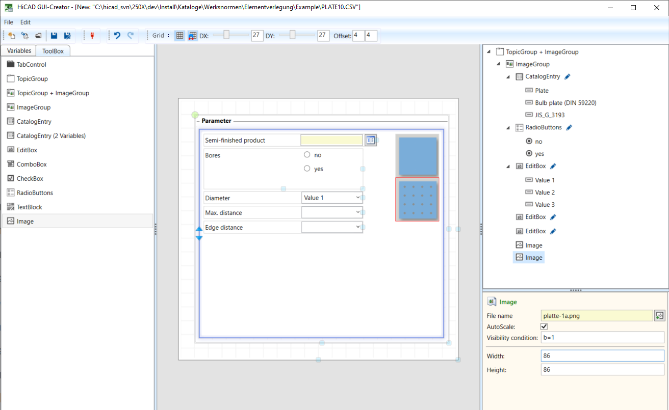
Step 5: Insert images
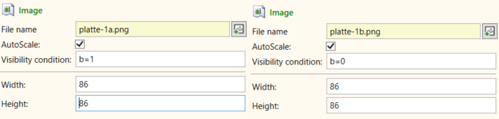
Now, insert 2 images, namely:
 for Bores: no
 for Bores: yes
This requires two Toolbox objects of type Image, which are simply dragged from the Toolbox into the ImageGroup.
For both images a visibility condition needs to be defined:
Schritt 5: Save the dialogue window and adjust the catalogue
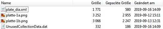
Now the dialogue window can be saved, e.g. with the name plate_dia.isdgui, in the catalogue Werksnormen\Elementverlegung\Example.
This file contains the used images, the dialog in XML format and the file UnusedCollectionData.dat with a list of unused variables.
To be able to use the dialogue window, it must be assigned to the corresponding installation element in the Catalogue Editor, e.g.
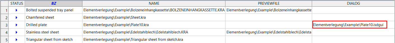
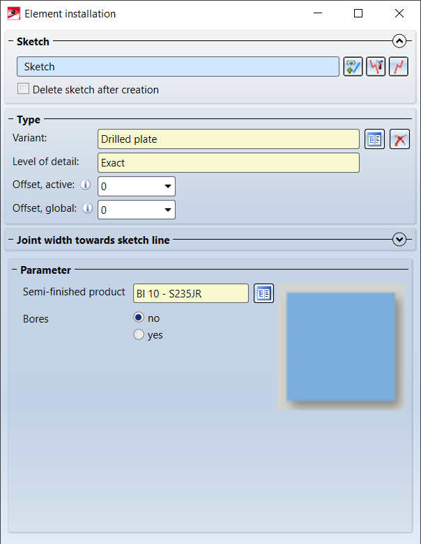
If now the installation element for element installation is selected, this dialogue will be displayed:
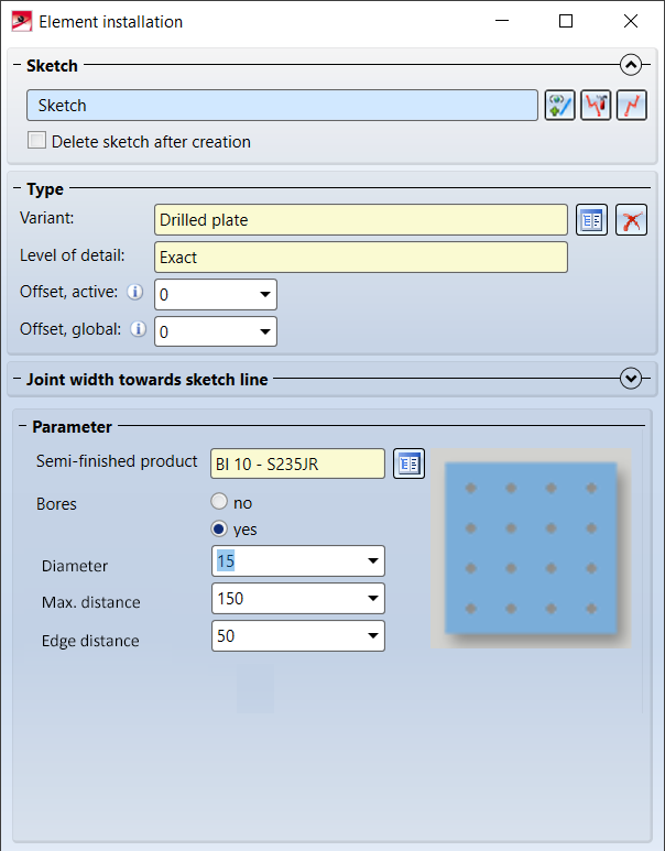
If the RadioButton Bores: yes is activated, the dialogue window looks like this:
For installation elements, additional conditions can be assigned to the variables used. In addition, you can define error messages that are displayed if the conditions are not met when the installation elements are installed. In this case the respective input field or the OK button is marked with the  or the
  symbol. If you move the cursor over the symbol, the error message is displayed. These conditions and error messages cannot be defined with the HiCAD GUI Creator, but must be entered in a separate file, the name of which is entered in the Catalogue Editor in the CONDITIONS column of the corresponding tables. You can find further information here.


The HiCAD GUI-Creator • Element Installation • Catalogue Editor
|
© Copyright 1994-2020, ISD Software und Systeme GmbH |
Data protection • Terms and Conditions • Cookies • Contact • Legal notes and Disclaimer