Project: HiCAD Element installation
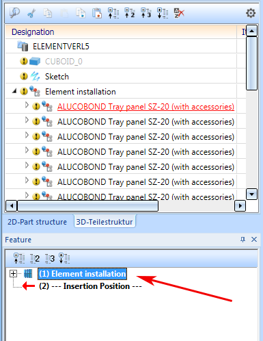
To edit installed elements, double-click the corresponding feature entry of the Element installation assembly. You can then change or delete installation elements, or add new ones.
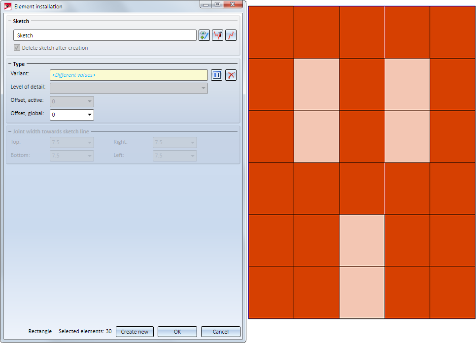
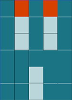
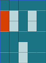
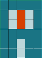
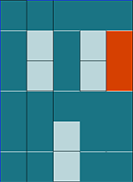
The Element installation dialogue window ill then be displayed. In the model drawing the still empty areas of the installation sketch, i.e. the areas where elements can still be placed, are shown in light orange. The dark orange areas are already occupied.
When installing elements - especially for complex facades - it is often the case in practice that certain installation elements have the same options. To make it easier to select the areas to be occupied (rectangular or polygonal sketch areas) and to edit installation elements with the same parameters, HiCAD offers the possibility to work with so-called selection groups. The advantage is that you can group installation elements with the same parameters and then select or deselect all elements of this group with one click. The Selection groups area is available in the Installation elements dialogue window.
Detailed information on working with selection groups can be found here.
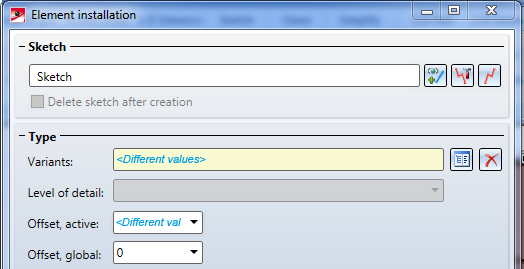
If the same settings apply to all already installed elements, these will be shown in the dialogue window. If the settings differ, the text <Different values> will be shown in the corresponding input field of the dialogue window.
You can select the different editing options without closing the Element installation dialogue window. All changes will only be applied after closing the window with OK or Reset.
Please note the following:
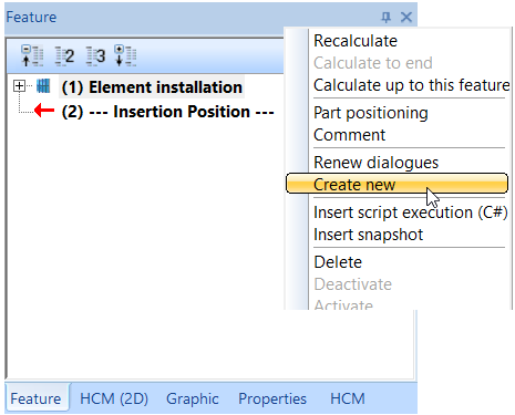
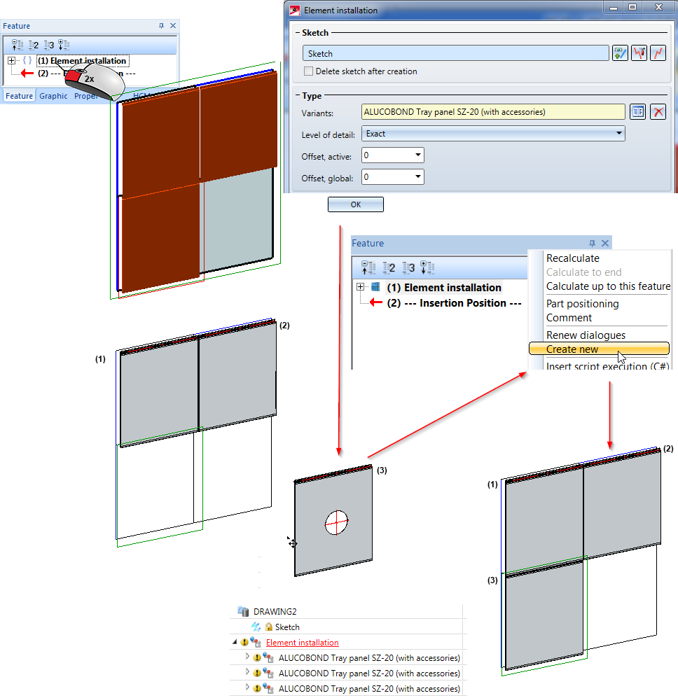
If you do not want this behaviour, click Create new instead of OK. If the dialogue window will be closed by clicking Create new , the following will happen:
The function has the following effect:
An example:
In the image below the two top fields and the bottom left field of the sketch have been occupied. The variant ALUCOBOND riveted has been chosen for the fields (1) and (2), and the variant ALUCOBOND Tray panel SZ-20 (with accessories) for the field (3) - each one with the default parameters. Then, the installation element ALUCOBOND_SZ20 (3) has been drilled and moved.
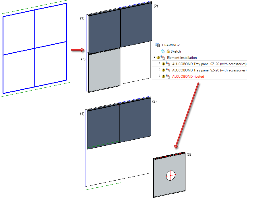
Now, the editing of the element installation via the Feature log can be started: The three marked elements are assigned the variant ALUCOBOND Tray panel SZ-20 - without changing any parameters. This means that nothing has changed for the installation element (3).
If the dialogue window is now closed with OK, only the installation elements (1) and (2) will be recalculated, while the displacement and the bore in installation element (3) remain.
If you then call the Create new function, all installation elements will be recalculated. Installation element will be reset to its previous position, its bore will be removed.
If installation elements are referenced, the Element installation feature will be deleted. This means that an editing via the Element installation dialogue window will no longer be possible.

To delete installation elements, select the elements with the cursor. The selected elements will be highlighted and can then be deleted with a click on the  symbol.
You have the following option to select the elements you want to delete:
will suffice. You can also mark several elements at once: You can
In the preview the elements will be immediately deleted by clicking the symbols. However, the actual deletion will only take place after confirming with OK.
 Please note:
If you want to place elements on still empty parts of the element installation sketch, or change already existing installation elements, proceed as described in the Element Installation: Basic Procedures topic.
Choose the desired sketch areas and specify the required settings. To select the elements, proceed as described in the Element Installation: Basic Procedures topic.
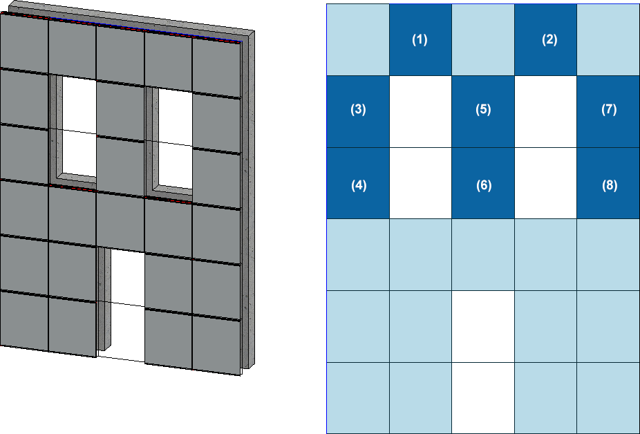
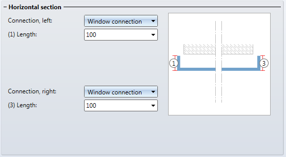
We will use the example from the Element Installation: Basic Procedures topic here. Let us assume that you want to change the installation elements of the dark blue areas (1) - (8): Instead of the standard design you want to use the window connection.
After double-clicking the Element installation feature entry, the following steps must be taken:
Step 1:
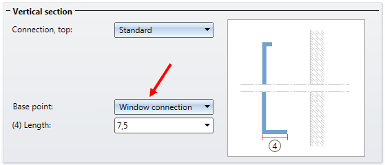
Step 2:
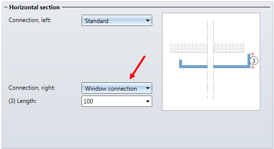
Step 3:
Step 4:
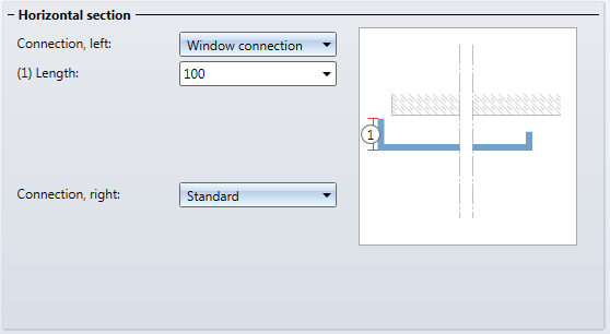
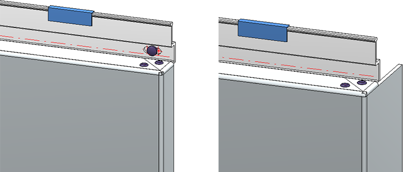
Left: Installation element (3), previously with type "Standard"; Right: Installation element (3) after its change to "Window connection"

Element Installation: Basic Procedures • Marking Colours • Element Installation: Example
|
© Copyright 1994-2020, ISD Software und Systeme GmbH |
Data protection • Terms and Conditions • Cookies • Contact • Legal notes and Disclaimer