
Project: HiCAD Sheet Metal
Sheet Metal > Sheet development > Export individual development
Use this function to export a develeopment as:
When exporting a development as DXF/DWG (AutoCAD) file, you have the option to:
Proceed as follows:
The standard dialogue window for the saving of a file will be opened. On the right hand side you can choose the export settings.
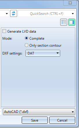
 checkbox if you want to additionally output an XML file for CADMAN-B (from Version 7.5 onwards).
 A prerequisite for the output of LVD data is the assigning of bending tools to the bend zone with the Bend zone tooling  function.
If LVD data generation has been activated, only the complete development can be exported.
For the DXF export you will need the file HCADACAD.DAT. This file contains:
The file can be customized and is located in the HiCAD SYS directory. After customization, do not save the file with the extension .DAT, but with .DA1, .DA2 or .DA3. For the export of developments to COBUS NCAD use the file HCADACAD_COBUS.DAT in the HiCAD SYS directory. If you want to use this file, save it with the matching file extension (e.g. HCADACAD.DA1).Click here for more information.
When outputting GEO data, the assignment from the file CAMIntHICAD_TEO.ini will be evaluated.
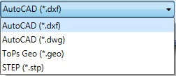
If you choose the STEP format instead, you have the following options:
|
Transfer layers |
The layer on which the edge is located (e.g. bend lines on Layer 2) will be transferred during export. |
|
Transfer colours |
The colour will be transferred during export. If you have deactivated this option, you cannot use the Export fits information via surface colour option (see below). |
|
Export fits information via surface colour |
By activating or deactivating this checkbox you can determine whether fits information are to be exported by means of a surface colour. For this to happen, the Transfer colours checkbox (see above) needs to be deactivated. The diameter of the corresponding bore will then be highlighted in a different colour in the imported STEP part. In the SYS directory of your HiCAD installation you find the configuration file FITINFO_COLOR.DAT, in which it is determined which RGB value are to be assigned to which fits information. |
|
Export free points |
By activating or deactivating this checkbox you can determine whether the exporting of free points in the model drawing should be allowed or suppressed (if they could cause problems in other places). |
|
Export free edges |
By activating or deactivating this checkbox you can determine whether the export of free edges in the model drawing should be allowed or suppressed (if they could cause problems in other places). |
|
Thread body |
Choose As separate parts or United with parent part if you want thread bodies to be exported as individual parts or united with their superordinate part, respectively, in the model drawing. Choose Do not transfer if you do not want the thread bodies to be exported. |
If you choose ToPS GEO, you can determine via the Export forming edges option, whether processings (forming tools, cross-breaks) are to be considered for export.
The configuration of the file name takes place via the file SheetToDXF.FTD. You can customize this file in the Annotation Editor if desired. If this does not result in a proper name, the name will be "Sheet".
If you have created the development with the settings for, e.g., LVD, Bystronic, Cobus or Lantek Expert, the parameters will be considered for the DXF export.
(1) Section contour
(2) Complete
![]() Please note:
Please note:
In developments, threads are saved as sub-parts. This structure will be considered in the sheet for the DXF export.


Extras (3-D SM) • Development (3-D SM)
|
© Copyright 1994-2020, ISD Software und Systeme GmbH |
Data protection • Terms and Conditions • Cookies • Contact • Legal notes and Disclaimer