
Project: HiCAD Sheet Metal
Example: Assign bending tool and export development
Example: Development with output of die and punch
Sheet Metal > Further functions > Extras  > Bend zone tooling
The Bend zone tooling function enables a practice-oriented adjustment of the radius and the allowance method.
In practice, the bend radius depends on various factors, such as the sheet material, the sheet thickness, or the bending tools used. This can be taken into account by means of the Bend zone tooling function, which enables a practice-oriented adjustment of the radius and the allowance method. The data of the machine manufacturer LVD will be evaluated for this purpose.
The LVD group offers a comprehensive product portfolio ranging from machine tools and software solutions for sheet metal processing, including laser cutting systems, punch presses, folding presses, guillotine shears and automation systems.
 Please note:
The input data for the converter are not supplied by the ISD. For the generation of these data, please use the LVD CAM program CADMAN-B. If you have any questions concerning the generation, please contact our Consulting team.
The following example describes the procedure of using LVD data for the adjustment of bend zones and the export of the development from HiCAD to CADMAN-B (from Version 7.5) by LVD.

When assigning LVD tools to bend zones, bend radii and allowance methods will be adjusted.
The bend radius will then result from the following factors:
The allowance method results from the Material (LVD designation).
The changed bend radii and allowance methods will be entered into the feature parameters of the sheet. Supported are only functions for which bend radii and allowance methods are recorded in the feature logs. Currently supported are bend zones which are created with the following functions:
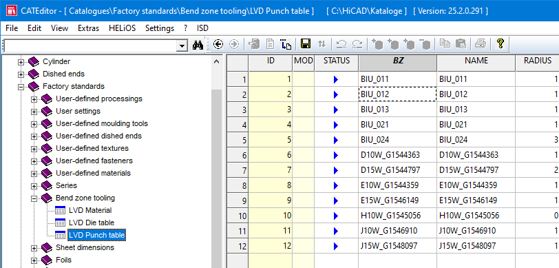
The data for bend zone tooling can be found in the Catalogue Editor, at Factory standards > Bend zone tooling.
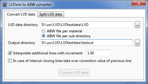
The allowance data (ABW files) are generated with the LVDxmlToABWConverter.EXE tool. (hicad/exe directory). The converter combines the XML files of a directory or of a material, and generates the ABW file from them. For the generation of these data, please use the LVD CAM program CADMAN-B. If you have any questions concerning the generation, please contact our Consulting team.
Proceed as follows:
|
Interpolate additional lines ... |
Additional lines are interpolated in the ABW files, in order to bridge the discreet values for sheet thickness, bend angle and inner radius from the XML files, each at a distance of the specified increment. |
|
In case of interval closing lines... |
When completing a value range in a column of the ABW file (column with 999), the correction value of the previous line will be taken over or set to 0. |
Use the Split LVD data tab of the LVDxmlToABWConverter.EXE tool to split the XML files exported from CADMAN, i.e. to create separate XML files per material and and sheet thickness (Filename [Material]_[Sheetthickness].xml). The split XML files serve as input source for HiCAD. Furthermore, they can be used for the ABW file per sub-directory mode during conversion. The path to the files must be specified in the Configuration Editor, at Sheet Metal > Bend zone tooling.
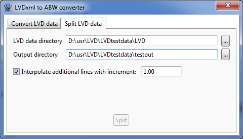
Activate the Interpolate additional lines with increment: checkbox to calculate additional intermediate values for the data in the ABW file.
Example:
The values for bend angles in the LVD data are 10°, 20°, etc.
If the increment is 2, the values for 12°,14°,16°,… will be entered into the ABW file.
In the Configuration Editor, select Sheet Metal > Bend zone tooling and adjust the following parameters as follows:
For the later DXF export with bending data the HCADACAD.DAT file needs to be adjusted accordingly. HiCAD creates outer contours and bend lines in different colours. For the export you need to specify that the HiCAD colours are to be assigned to the corresponding DXF layers. Bend lines and bend line texts are located on the BENDS layer, everything else on the OUTLINE layer.
The following settings in the HCADACAD.DAT file need to be adjusted or added:
TPOINT 1 # Retain text reference points Text-Bezugspunkte beibehalten
(Adjust value) The parameter TPOINT (# Retain text reference points/ Text-Bezugspunkte beibehalten) should be set to 1, to retain the alignment (for Bystronic: "Centred") of the bend line texts in the blank for the export to the DXF format. Centred bend line texts will then retain their insertion point on the bend line mid point. Hence, centred bend line texts will retain their insertion point in the middle of the bend edge. If the parameter is missing, or if the value is not 1, the texts will be aligned left for DXF export. This may result in failed text assignments if a displaced insertion point is located outside the edge.
FIGBL 0 # Figure block transfer (-1/0/1) Figur-Block Uebertragung (-1/0/1)
(Adjust value) The parameter needs to be set to 0 for LVD export.
BYLAY 4 CONTINUOUS BENDS
BYLAY 3 CONTINUOUS OUTLINE
(Add lines)
LAYER 9999 004 0 00 BENDS
LAYER 9999 999 0 01 OUTLINE
(Add lines)
TXTLA 9999 004 BENDS # LAYER: 1-4=layer 5-7=colour, layer name
TXTLA 9999 999 OUTLINE
(Add lines)
#STYLE T1 ARIAL arial.ttf 1.0 # STYLE: No., text style, font file, width correction
#STYLE T3 "ARIAL Narrow" ArialN.ttf 0.95 # STYLE: No., text style, font file, width correction
STYLE T1 ARIAL STANDARD 1.0 # STYLE: No., text style, font file, width correction
STYLE T3 "ARIAL Narrow" STANDARD 1.0 # STYLE: No., text style, font file, width correction
(Change or comment out lines) The lines beginning with STYLE determine the settings for the font. For example, if Arial is to be used as default font, it can be set as "STANDARD" for the export. The existing entries are to be changed or commented out accordingly.
COLOR 5 0
(Adjust value) When this value has been set, bend line texts will be output in yellow by default. If you want them to be output in a different colour, change the value accordingly.
Use the Default setting  function (Sheet Metal > Sheet development > Update > ...) to specify the blank parameters. Click the Favourites
  icon to choose the desired settings, e.g. for LVD machines.
The Favourites delivered with the software are only examples and may require adjustment to your (LVD, Bystronic etc.) machines.
As the export is done via DXF, the HCADACAD.DAT is also of significance here.
The development parameters are saved for new developments to be created in the drawing. For created developments the settings are stored in the developed part and can be modified via right-click and Change development.
> Bend zone tooling . If the settings had been adjusted as described above, the following dialogue window will be displayed:
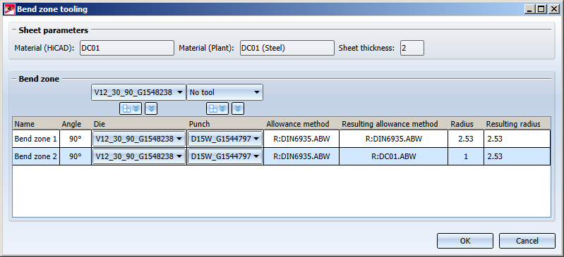
In the Bend zone area you can select a default tool. The default setting can be applied to  ALL or
  only SELECTED bend zones.
To obtain annotations according to LVD, select the Favourite  LVD for the development.
 function (Sheet Metal > Sheet development) to create an unfolded blank of the sheet metal part.
 Please note that dimensions will be ignored in LVD annotations.
The sheet metal development will be exported from HiCAD in the form of XML data (*.CBBatchInput) for CADMAN-B (from Version 7.5) by LVD and as an DXF file.
 function ( Sheet Metal > Sheet development) and select a directory for the DXF and XML file (*.CBBatchInput).
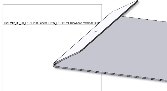
The bend tools Die and Punch defined in the LVD Bend zone tooling  can be displayed in the development bend line text.
The selection is made in the development settings when editing the bend line texts.
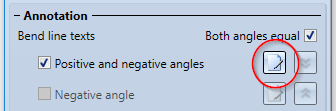
Then select the Die and Punch attributes in the text editor.
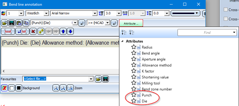
If an assigned tool exists for the bend zone, the names of these tools can now be inserted in the bend line texts.
The names are the entries in the BZ column in the corresponding bend tool assignment tables "LVD Die - Table" and "LVD Punch - Table" from the Catalogue Editor.

|
© Copyright 1994-2020, ISD Software und Systeme GmbH |
Data protection • Terms and Conditions • Cookies • Contact • Legal notes and Disclaimer