Project: HiCAD Sheet Metal
HiCAD has libraries of bore patterns (e.g. Agrafes) and punches. To expand the libraries you can use
(please also see Bore Patterns in 3-D).
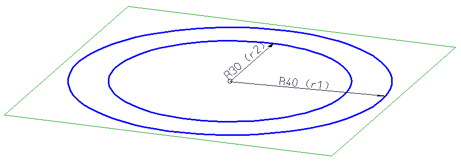
The following example uses the contour shown below as a bore pattern in different sizes.
Example 1: Create 2-D part > Parameterize > Add bore pattern to catalogue > Insert new bore pattern

 to create an empty 2-D part, e.g. Ring01.
  > CP-P
  . Draw a circle with a size of 30, and a second circle with a size of 40 with the same centre point.
  .
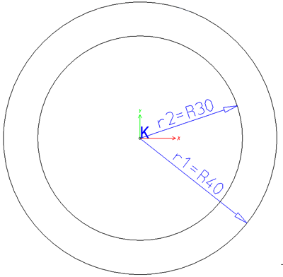
.  function beneath Transform. Then, select the isolated point and move it to the absolute point (0, 0).
> Delete variables  . > Concentric
  and identify the two circles. > Radius
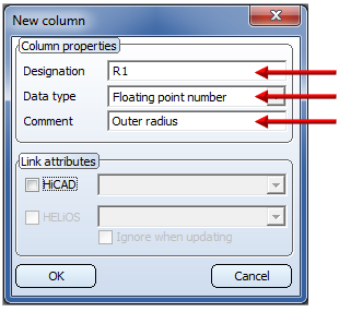
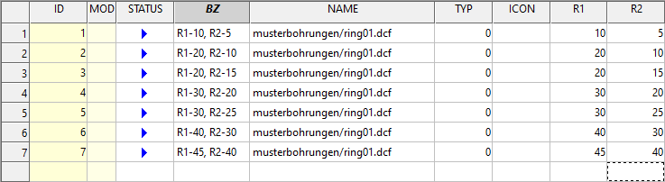
  to assign the positional constraint to the elements. Identify the outer circle, enter r1 instead of a value input, and 40 as the variable for r1. Identify the inner circle, enter r2 and 30 as the variable.
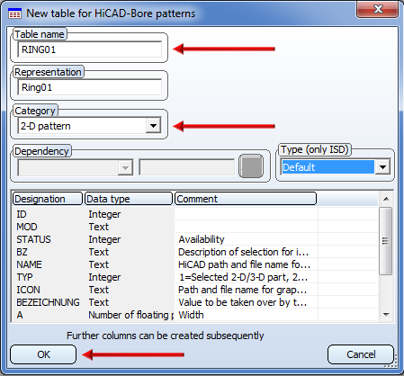
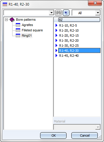
> Without database  , e.g. with the name Ring01. Select the HiCAD folder KATALOGE/WERKSNORMEN/MUSTERBOHRUNGEN as storage location.
 program in the HiCAD EXE directory.
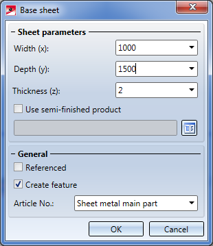
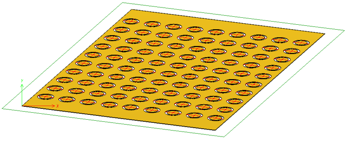
 . Enter the desired dimensions in the dialogue window, e.g. Width 1000, Depth 1500 and Thickness 2. Confirm with OK. Specify the two fitting points for the base sheet in the drawing via right-click.
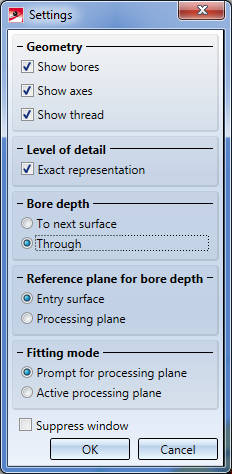
 function (3-D Standard > Standard Processings > Bore > ...).
 button and enter the number of bores in X- and Y-direction, e.g. nx: 10 and ny: 9 an. For the distance in X-direction enter dx: 130 and click the
  icon to apply the same value to all bores in X-direction. For the distance in Y-direction enter dy: 110. Here, too, click the icon.
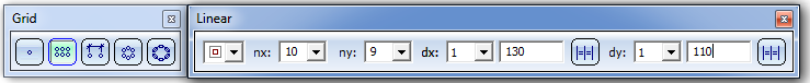
The fitting grid determines the distance of the bores in X- and Y-direction, respectively. The value can be specified individually for each row/column.
 and, in the displayed pocket calculator window, click OK. Identify the upper left corner of the sheet. The pocket calculator will then prompt you to specify the X- and the Y-value. Enter 750 for X, 500 for Y and 0 for Z and confirm with OK.
 You can then insert the bore again, change the parameters via right-click, or end the function by pressing the middle mouse button.

Further Tools (3-D SM) • Bore Pattern (3-D SM)
|
© Copyright 1994-2020, ISD Software und Systeme GmbH |
Data protection • Terms and Conditions • Cookies • Contact • Legal notes and Disclaimer