Drawing Derivation - Settings for: Drawing Sheets, View Groups, Views + Sheet Developments
Drawing > Itemisation/Detailing > Drawing derivation 
In the Drawing parameters of the Derived drawing dialogue window, you can specify various settings which influence the layout and representation of the derived drawing. These settings can be specified for:
by clicking the corresponding button.
The presettings of the dialogue windows will be specified in the Configuration Editor, at Automatic drawing derivation > Production drawing.

Settings for Drawing Sheets
In this dialogue window you specify the settings for the sheets of a derived drawing.
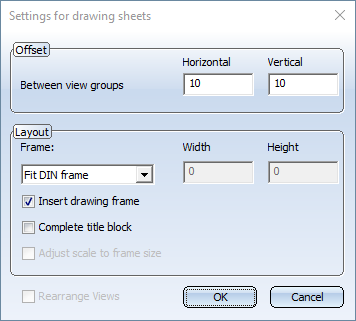
- Distances
Specify the horizontal and vertical distance between the view groups. - Layout
Here you specify the size of and the frame for the drawing sheet. - User-defined
The sheet size will be defined by explicit specification of width and height. If the Adjust scale to frame size checkbox is active, the view groups/views generated by the derived drawing will be automatically scaled in such a way that they fit into the created drawing frame. Please note that this setting can slow down the drawing derivation, as an optimally scaled arrangement will require multiple scaling of all generated views.
- DIN_...
The sheet size will be defined by the size of a predefined DIN frame, e.g. DIN_A3. If you want the scale of the view groups/views to be automatically adjusted to the frame size, activate the Adjust scale to frame size checkbox. - Fit DIN frame
If you select this option, HiCAD automatically selects a DIN frame which contains the created view groups entirely and in an unscaled state. The Adjust scale to frame size option checkbox will be greyed out when this option is selected.
In addition, you can specify for DIN formats that an appropriate drawing frame will be inserted and the corresponding title block will be filled in automatically.
 Please note:
- The derived drawing will be spread over several sheets if required.
- When arranging view groups on a drawing sheet, the representation of BOMs and title blocks will be automatically taken into account as well (if you activated the representation of these elements).
- In the Configuration Editor you can optionally specify HiCAD or Windows paths for drawing frames. To do this, select ... > Automatic drawing derivation > Production drawing > Drawing frame > DIN... > Figure name. In the Value field you can precede the figure name with the path. (SP1)
Examples:
- DINA4
File DINA4.FIG from the HiCAD file group C: (this is the path entered for C: in the system file Filegrup.dat) - X:DINA4
File DINA4.FIG from the s der HiCAD file group X (this is the path entered for C: in the system file Filegrup.dat) - C:\TEST\DINA4
Datei DINA4.FIG in the Windows folder C:\TEST
Furthermore, you can also configure additional drawing frames there: Use the Derive structure function to derive further frames from the DIN_A0 frame, and configure them.
Settings for View Groups
In this dialogue window you specify the representation of view groups.
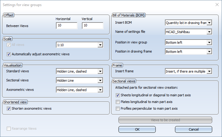
- Distances
Specify the horizontal (1) and vertical (2) distance between the views of a view group.
- Scale
Select the desired scale in the listbox. If you want axonometric views to be automatically adjusted, activate the corresponding checkbox. The axonometric view will then be adjusted in such a way that is will not require more space than the rest of the view group. A typical use case would be a beam or profile in shortened representation. In such cases the unshortened axonometric view will be downsized.
The All views checkbox is only active for subsequent changes of settings!
- Visualisation
Specify the visualisation type of the views: - Glass model,
- Hidden Line or
- Hidden Line dashed.
The visualisation can be specified separately for standard views, sectional views and axonometric views. Default values are:
- Standard views: Hidden Line dashed
- Sectional views: Hidden Line
- Axonometric views: Shaded with edges
The All views checkbox is only active for subsequent changes of settings.
- Beam shortening
Please note the following:
These shortenings of views will not take effect in axonometric views with shaded representation. Furthermore, it can happen that beams are not displayed in shortened representation if the Automatically adjust axonometric views in the Scale area has been activated. In this case it may be possible that a scale for the axonometric view will be found that does not lead to a shortening according to the selected shortening parameters.
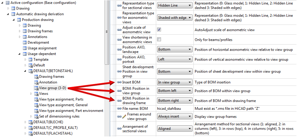
- Bill of Materials (BOM)
Here you specify whether a BOM is to be placed into the view group of an assembly and if so, the position of that BOM.
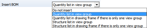
The following settings are possible:
- Do not insert
No BOM will be inserted.
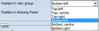
- Quantity list in View group/Structure list in view group
A Quantity or Structure list will be inserted within the view group. The position of the BOM is specified via the setting in the Position in view group listbox.
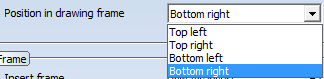
- Within drawing frame if only 1 view group
If only one view group is created, the BOM can also be placed in the drawing frame.
The layout of the BOM can be chosen from the corresponding listbox under Name of settings file.
Type and position of the BOM can be defined separately for each usage in the Configuration Editor at Automatic drawing derivation > Production drawing > Usage-dependent > .... > View group. If the drawing parameters are loaded from a configuration that has been saved in the Configuration Editor, the corresponding settings from the Configuration Editor will be will be preset in the dialogue window.
To change the position of the BOM in the view group subsequently, open the Drawing tab and choose Itemisation/Detailing > Derive > Change settings - Active view group, provided that a BOM had been created in this view group.
- Frame
View groups can also obtain a drawing frame. The following options for drawing frame insertion are available: - Do not insert
- Always insert
- Insert, if there are multiple view groups
The default setting is Always insert. This presetting can be changed in the Configuration Editor, at Automatic drawing derivation > Production drawing > Usage-dependent > ... Frames around view group.
- Sectional views
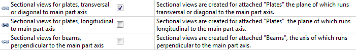
If the Sectional views checkbox has been activated for in the Views for assemblies dialogue window, you can specify in the settings for view groups whether sectional views are also to be created for attached parts. This is possible for:
- Steel Engineering plates running transversely or diagonally to the main part axis,
- Steel Engineering plates running longitudinally to the main part axis and
- Beams running perpendicular to the main part axis.
According to the ISD default setting, sectional views are automatically created for Steel Engineering plates running transversely or diagonally to the main part axis. When working with configuration templates, you can specify for each usage which sectional views are to be created for attached parts. The setting can be defined in the Configuration Editor at Automatic drawing derivation > Production drawing > Usage-dependent > name > View group, with name being the name of the relevant template.
Please note:
- When arranging view groups on a drawing sheet, the representation of BOMs and title blocks will be automatically taken into account as well (if you activated the representation of these elements).
- If a drawing frame contains only one view group, it will be centred in the drawing frame. You can change this behaviour in the Configuration Editor, at Automatic drawing derivation > Production drawing > Drawing - Centre individual view group. If you deactivate the checkbox, individual view groups will be placed at the top left of the drawing frame. If a centred position would lead to collisions, e.g. with the title block, the view group will be automatically placed at the top left.
- The frame of a view group can also be manually deleted if desired. To do this, right-click the frame and choose Delete frame.
- Colour, line type and layer of frames for view groups can be specified in the Configuration Editor, at System settings > Visualisation > View group.
Settings for views
Here you specify the settings for views, e.g. the type of dimensioning, the representation of designation tags, the part environment (adjacent parts) etc.
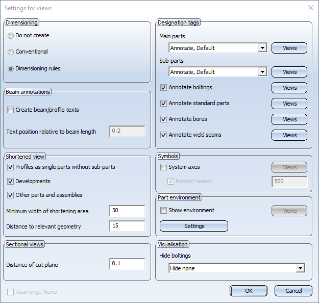
- Dimensioning
The views of the workshop drawing can be dimensioned automatically. The following options are available:
Do not create
If you do not want a dimensioning, activate this option. However, please note the following:
- If the Drawing parameters: From configuration option has been activated, the Do not create option will only be considered if in the Configuration Editor the Create dimensioning parameter at Automatic drawing derivation > Production drawing > Usage-dependent > NAME > Views has been set to No (NAME = Name of the selected configuration).
- If the Drawing parameters: Set in dialogue option has been activated, the Do not create option will only be considered if in the Configuration Editor the Create dimensioning parameter at Automatic drawing derivation > Production drawing > Usage-dependent > Default > Views has been set to No .
Conventional
If this option has been selected, the settings of the Dimensioning Settings function at Itemisation/Detailing > Dim. > ... will be used. However, please note the following:
- If the Drawing parameters: From configuration option has been activated, the Do not create option will only be considered if in the Configuration Editor the Create dimensioning parameter at Automatic drawing derivation > Production drawing > Usage-dependent > NAME > Views has been set to Conventional (NAME = Name of the selected configuration).
- If the Drawing parameters: Set in dialogue option has been activated, the Do not create option will only be considered if in the Configuration Editor the Create dimensioning parameter at Automatic drawing derivation > Production drawing > Usage-dependent > Default > Views has been set to Conventional.
Dimensioning rules
Dimensioning rules are always part of a Configuration. If you have activated the Drawing parameters, From configuration option in the workshop drawing dialogue window, the dimensioning rules of the selected configuration (e.g. COLUMN/COLUMN) will be used. If the Drawing parameters, Set in dialogue option is active, the dimensioning is performed according to the rules of the DEFAULT Usage.
- Beam annotations
If you want the beam/profile annotation to be displayed, activate this checkbox. The position of the annotations is determined by the entered value.
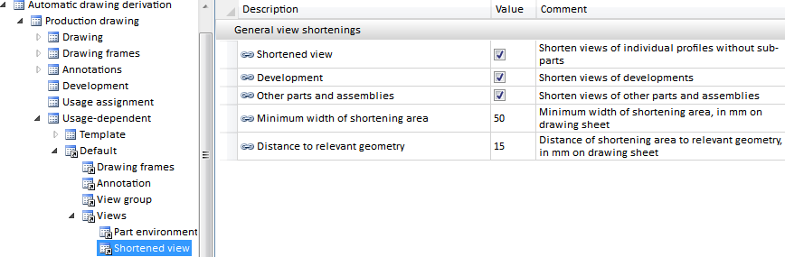
- Shortened view
- Show views of beams as shortened views
Beams can be shown in shortened representation in workshop drawings. The shortened representation is the ISD default setting. - Show views of development as shortened views
Also developments can be shown in shortened representation. The shortened representation is the ISD default setting. - Show other views as shortened views
If you want other views (e.g. views of Sheet Metal parts) to be shortened as well, activate this checkbox.
(1) Distance of shortening to relevant geometry
For the shortened representation you can specify the minimum width of the shortening area (= "disappeared" area) und the distance of the shortening to the relevant geometry.
If the settings for drawing derivation are loaded from a configuration, the settings specified in the Configuration Editor at Automatic drawing derivation > Production drawing > Usage-dependent > name > Views > Shortened view will be evaluated. name denotes the name of the corresponding usage.
If there are offset lines, the view will not be shortened!
- Beam shortening
Beams and profiles can be displayed as shortened representations in workshop drawings. You can specify the shortening factor (%) and the minimum shortening length for the shortened representation. - Sectional views
For attached parts, e.g. front-welded plates, you can automatically create the corresponding sectional view. The viewing direction of the sectional view is from the centre of the beam to the attached plate. The cutting line of the sectional view is created parallel to the attached plate. The distance from the attached element can be specified in the Distance of cut plane input field.
The created sectional views are sectional views with depth limitation. You specify via the Views to be created for: Assemblies option whether the sectional view will be created.
- Designation tags
In this area you specify, via activation of the corresponding checkboxes, which elements you want to annotate in which views. To select the views, click the View button and activate in the displayed dialogue window the required checkboxes. All annotations are automatically placed close to the part and are arranged collision-free. - Symbols
You can also display the system axes annotations, i.e. the axes of a Steel Engineering grid, in a workshop drawing if required. This is however only possible in views for assemblies.If this checkbox is active, you can specify, via a click on the View button, in which views you want to display the axes annotations. The axes of the grid sub-systems will also be considered in the process.
In addition, you have the option to narrow the search for system axes by activating the Restrict search checkbox and specifying the area for te search. The value determines the distance (1) from the beam start/end (HiCAD searches from the beam end to the outside for the next grid axis).
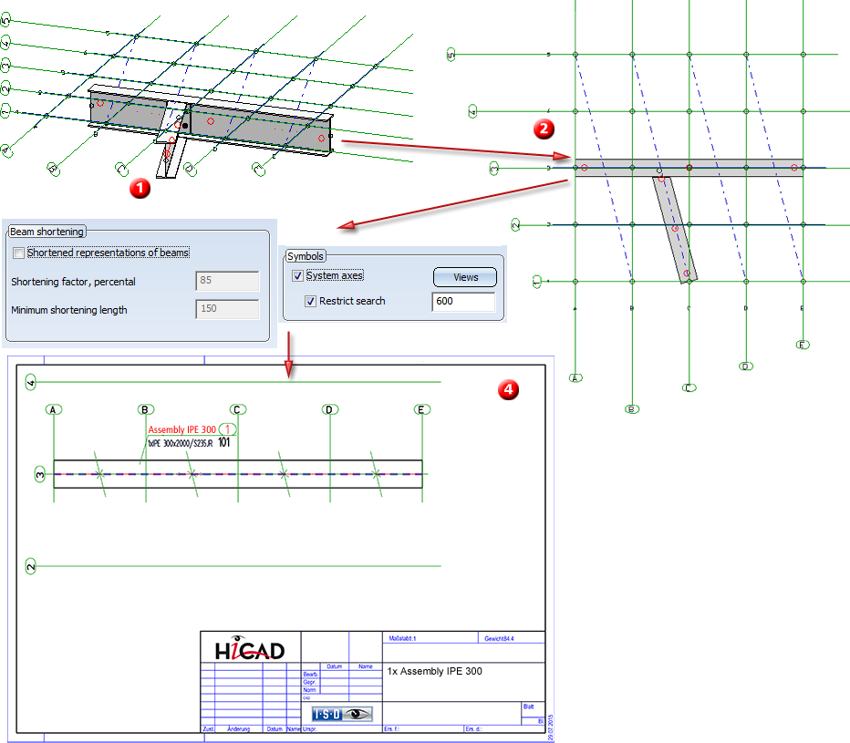
(1) Original construction with grid (Distance: 500) and Grid sub-system, (2) Top view, (3) Settings for views, (4) Detail drawing of beam
HiCAD displays the annotations specified in the grid parameters.
- Part environment
The environment of a part, i.e. adjacent parts within a specified area, can also be displayed in workshop drawings. To display the part environment, activate the Show environment checkbox. Click the View button to specify in which views you want to display the part environment.
The Settings tab enables you to set various parameters for the part environment, such as the area for adjacent part search, or the representation of the part environment.
Part search
Here you enter a distance value determining the area that is used for adjacent part search.
Limit view
If you do not want to display the entire part environment, you can limit the view. Activate the Limit checkbox and enter the values for the limitation. Elements outside the specified area will not be displayed.
Representation
Parts located within the selected area can be displayed in a different edge and surface colour.Activate the corresponding checkbox and select the desired colour. In addition, you have the option to make the parts transparent - independent of the layer selected.
- Visualisation
Here you can specify whether boltings are to be displayed in the views of the production drawings or not.
The following settings are possible:
- Hide none
No bolts will be hidden. This setting corresponds to the behaviour before HiCAD 2016 SP1. - Hide all
All bolts will be hidden. - Hide only "Site bolts"
Only bolts with the property "Site assembly" or "Site production" will be hidden.
You can preset the visualisation for each usage in the Configuration Editor, at Automatic drawing derivation > Production drawing > Usage-dependent > .... > Views. If the drawing parameters are loaded from a configuration that has been saved in the Configuration Editor, the corresponding settings from the Configuration Editor will be will be preset in the dialogue window.
Please note that these settings do not apply for bolts within structure assemblies (e.g. in the case of boltings that have been inserted as "loose parts"). These bolts will not be displayed in the workshop drawing.
When you update a production drawing, the settings that were active during creation of the drawing will be used.
Please note:
- AutoLabeling ensures an optimally arranged, collision-free placing of the designation tags close to the corresponding parts. This means that collisions (overlaps) of annotations, item numbers or dimensionings are prevented.
- If you use the dimensioning rules of one of the predefined configurations, and have activated the system axes, the distances to system axes are displayed as negative values for beams or profiles whose start or end is located between the system axes.
- If you use the drawing parameters of a configuration, the part environment will not be displayed by default. To change this, open the Configuration Editor (ISDConfigEditor.exe) and select ... > Automatic drawing derivation > Production drawing > Usage-dependent > Template > Views. Activate the Display part environment checkbox.
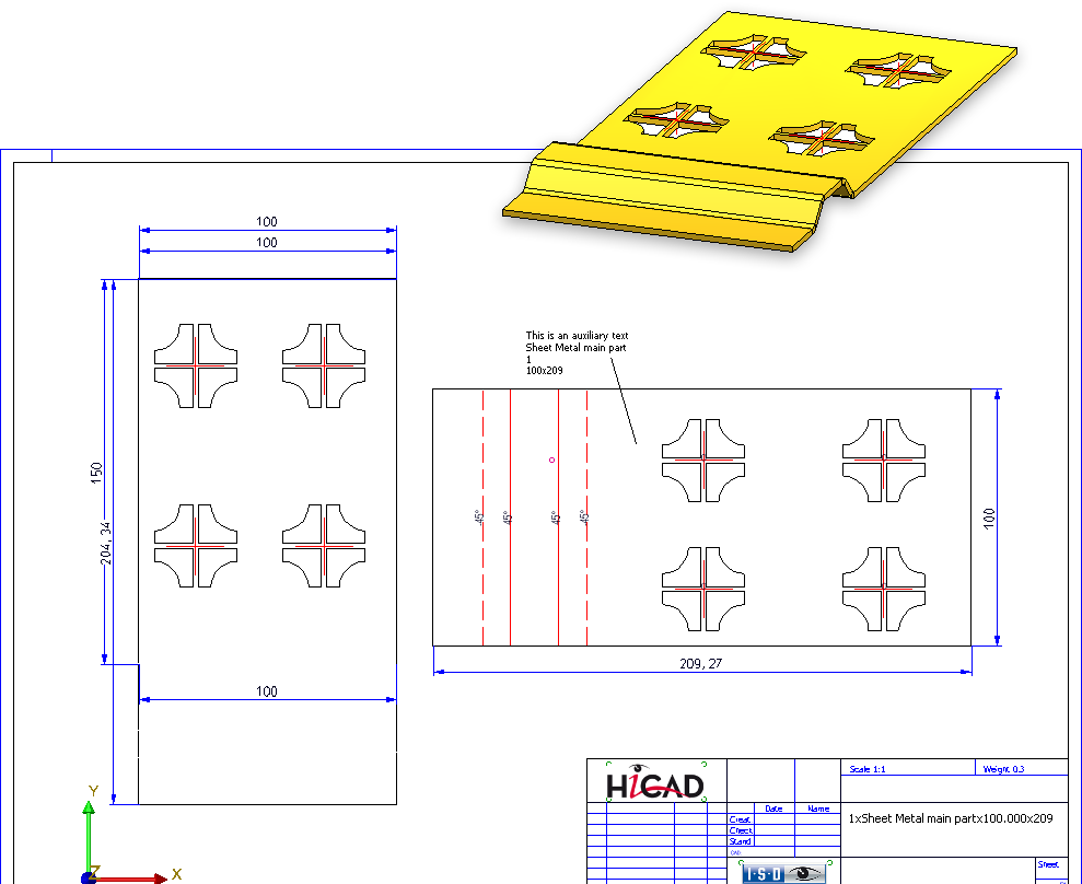
Settings for Sheet Developments
In this dialogue window you specify the settings for the development of sheet metal parts.
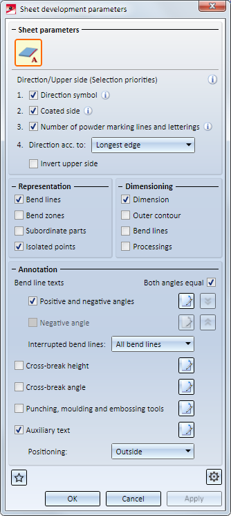
The settings correspond to those of the Development parameters function
Please note:
- AutoLabeling ensures an optimally arranged, collision-free placing of the designation tags close to the corresponding parts. This means that collisions (overlaps) of annotations, item numbers or dimensionings are prevented.
-
If you tick the Processings checkbox below Dimensioning, dimensionings will also be created for bores and subtractions. The following must be considered: If the checkbox Separate chains of dimensions for bores and subtractions is activated from the tab Bores/Boltings of the function Drawing > Itemisation/Detailing > Dim... > Dimensioning Settings, separated chains of dimensions for bores and subtractions will be created.
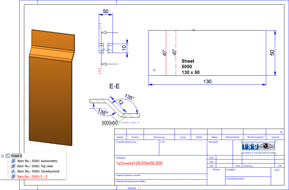
Settings for sectional views of sheets
In this dialogue window you can specify the settings for sectional views of sheets.
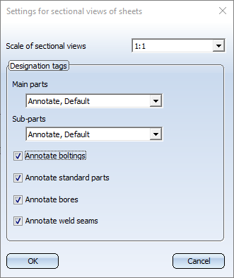
The following settings are possible:
- Scale of sectional views
- Main parts / Sub-parts
Here you select whether and how main parts and sub-parts are to be annotated in the sectional views. Possible settings are: - Do not annotate
- Annotate, Default
The default template for sheet metal parts is used for the annotation (PosNummer_Kantblech.ftd). - Annotate, acc. to usage
The usage-dependent templates for sheet metal parts are used for the annotation (POSNUMMER_VERWART....DEFAULT(KANTBLECHE).FTD). If these templates are not available, the default template is used. - Annotate boltings, standard parts, bores, weld seams
Using the checkboxes at the bottom of the dialogue window, you can specify whether or not boltings, standard parts, bores and weld seams are to be annotated in the sectional views.
![]() Please note:
Please note:
the viewing direction of the sectional views of sheet metal parts in the workshop drawing is to the right or downwards. Aligned cuts are accordingly to the right or below.

Derive Drawing • Derived Drawing: Change Settings • Derived Drawing - Views to Be Created • Usage-Dependent Configurations • Definition of Scales