Part Properties and Part Attributes
Every 2-D and 3-D part has certain properties. These include attributes, which influence the appearance and shape of the part and its geometry elements, and non-graphical information, which is taken into account, for example, in BOM creation. A distinction is made here between element or line attributes and the part properties and attributes.
The element attributes - colour, line type and layer - influence the display of individual geometry elements of a part. You can use these attributes, for example, to hide parts of your drawing temporarily, which may be useful for editing complex drawings in many cases. You can easily change the element and line attributes in Element snap mode by right-clicking the relevant element and then choosing Properties in the context menu.
Part properties describe the actual part. 2-D part properties include, for example, the overlap level or the material. The material, the surface and the part variables are examples of 3-D part properties. Furthermore, you can assign 2-D and 3-D parts other non-graphical information, the so-called part attributes, which is taken into account, for example, in BOM creation. Examples include the number, item, description or part type. This is particularly relevant if you are working without the PDM system HELiOS.
Part properties
To change the properties of a part, proceed as follows:
- Right-click the part in the drawing or in the ICN (in object snap mode).
- In the context menu, select Properties.
- Choose the desired function.
For active parts these functions are also available on the 2-D Part and 3-D Standard tabs:
|
|
2-D Part Properties > Attr. |
|
|
3-D Standard > Tools > Attr. |


Clicking  opens a pull-down menu with further functions.

Part attributes
2-D Part Attributes  / 3-D Part Attributes
You use the Part attributes function to assign a part non-graphical attributes, e.g. number, position, designation or part type, which are taken into account in BOM creation. This is particularly relevant if you are working without the HELiOS PDM functions.
- Enter the desired additional information.
- Apply the entered data by clicking the OK button or pressing ENTER (Return). The ESC key or the Cancel button cancels the function without applying the changes.
The function is available in the context menu as well as in the 2-D Part and 3-D Standard tabs.
![]() Please note:
Please note:
- The part attribute mask can also be opened by double-clicking the desired part in the drawing.
- Fields highlighted in a different colour are read-only fields. Data inputs are not possible here.
- If you assign the attribute Article numberto a part, the part structure of the ICN displays this designation instead of the part name.
- Designation 1 and the Item No. are displayed in curly brackets behind the part name/the designation in the part structure of the ICN.
- For certain parts, e.g. steel engineering beams or standard parts, the part attributes are assigned automatically.
- If you are working with HELiOS, the attribute BOM-relevant is automatically assigned to all parts with an article master.
- The Usage attribute enables you to define parts as columns, girders, transoms etc. ISD supplies various, predefined Types of use, which can be individually expanded and customised at any time. The Types of use are managed in the Factory standards > Usage catalogue of the Catalogue Editor. Further information on the Catalogue Editor can be found in the corresponding Online Help.
 During automatic itemisation you can automatically assign the types of use Girder (beam) assembly or Column assembly to Steel Engineering assemblies. For this to happen, open the Configuration Editor and set the parameter at Steel Engineering > Types of use accordingly.
- Assign types of use COLUMN or BEAM (girder) automatically
If this checkbox is active, the Girder (beam) assembly or Column assembly usage will be automatically assigned to Steel Engineering assemblies during automatic itemisation - depending on the position of the Steel Engineering main part in the assembly. The checkbox is deactivated by default. - Alignment for columns
Here you select the axis for the alignment of the columns (Default: Z-axis). Beams with this alignment will be recognized as columns, beams standing perpendicular to them as girders. - Allowed angle deviation of beams from defined alignment (in degrees)
This value determines up to how many degrees the axis of a beam is allowed to deviate from the axis specified at Alignment for columns parameter for the beam to be still recognized as a column (Default: 0).
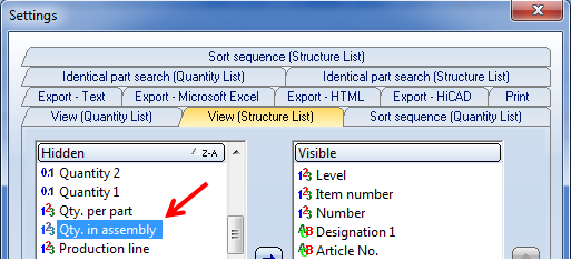
- Besides the Qty. per part attribute, a part attribute called Qty. in assembly is available. Here, the quantitative occurrence of a part in an assembly is detected. Only the active assembly will be considered.
Please note that the calculation of this value depends on the setting in the Configuration Editor, at Modelling > Part properties > Calculate quantity in assembly.
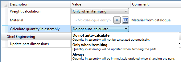
The default setting is Do not auto-calculate. If the value is to be automatically calculated, we recommend choosing the Only when itemising option. As the calculation refers to the item numbers, items without valid item numbers will have no effect.
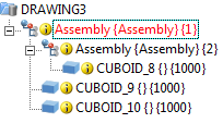
Example:
A drawing contains one assembly with three identical parts, one of which belongs to a subordinate assembly:
|
|
Part attribute |
|
|
|
Quantity in |
Total |
|
|
CUBOID_8 |
1 |
3 |
|
|
CUBOID_9 |
2 |
3 |
|
|
CUBOID_10 |
2 |
3 |
|
This part attribute can, for instance, be used for annotations or in BOMs.
If a drawing is active that has been created with the functions of the Management + BIM module, the Item number field in the Part attributes dialogue window will be locked.

ICN • Bills of Materials (BOMs) • HELiOS PDM Functions • System Attributes