Set down-grade symbol
Isometry + Pipe spool drawing > Symbols > Set down-grade symbol 
Use this function to manually insert a down-grade symbol into an isometry.
Specify the exact location where you want to place the symbol. The following options are available:
- Selection acc. to part (Default setting after function call)
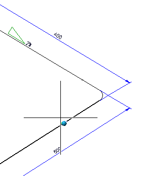
Here the point is located on a part. Move the cursor over the parts of the isometry. The location where the down-grade symbol is to be created will be marked with a coloured sphere (Special colour Marking 3). If you move the cursor near a part that allows no placing of down-grade symbols (e.g. the arc in the image below), the nearest possible location will be searched and highlighted.
Click to apply a point that is marked by a coloured sphere symbol. The Down-grade symbol dialogue window will then be displayed.
- Selection acc. to points
As long as you are asked to place the down-grade symbol (i.e. as long as the Down-grade symbol dialogue window has not been opened), you can right-click to open the following context menu:
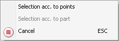
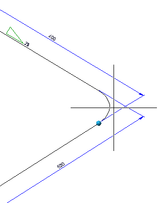
There you can find the Selection acc. to points function. When you call this function, HiCAD will mark - depending on the current cursor position - all start points and end points of the straight lines and arcs of the part (Special colour Marking 1).
You can now specify any point using the Autopilot or the Point options. This point needs not necessarily be located on the part. After specifying the point, the Down-grade symbol dialogue window will be displayed. If you want to go back to the Selection acc. to part mode before specifying the point, right-click and choose the function in the context menu.
Select Cancel or ESC to cancel the function.
As soon as you have specified a point for the placing of the symbol, the Down-grade symbol dialogue window will be displayed.
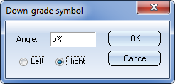
The Angle input field contains the annotation which will appear next to the down-grade symbol. This text will be generated from the text defined in the Settings for symbols, taking the down-grade of the selected pipe part into account. Beneath this input field you can select the direction in which you want the symbol to point. This direction, too, will be preset according to the selected pipeline.
When you click OK, the symbol will be created with a defined distance to the line element representing the pipeline. The symbol will be automatically aligned parallel to the selected straight pipe.
The function remains active, i.e. you can place further down-grade symbols if desired. To end the function, press the middle mouse button.
 Please note:
- The down-grade value can be entered in degrees (°), in percent (%) and in mm/m. This unit of measurement can also be output next to the value at the symbol.
- You can also call the function via the context menu of the pipeline (right-click pipeline).
- The properties of the symbol can be defined in the Settings for symbols.
- The distance to the line element representing the pipeline defined in the Settings for symbols will be considered when the symbol is placed in the drawing.

Delete down-grade symbol
Isometry + Pipe spool drawing > Delete > Delete down-grade symbol 
If no pipeline has been activated yet, use the cursor to select a part of the pipeline that you want to process. When you are asked whether the correct pipeline is active, answer with Yes.
Select the down-grade symbol with the cursor. It will then be deleted.
You can also call the function via the context menu of the pipeline (right-click pipeline).
Move down-grade symbol
To move a down-grade symbol, right-click the symbol and select
 Move
Move
in the context menu.
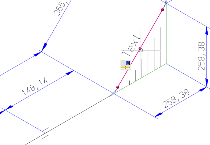
The symbol will then be attached to the cursor and can be moved freely. Click to specify the new position of the symbol.
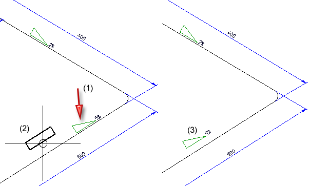
(1) Selected symbol, (2) Symbol attached to cursor, (3) New position of symbol.

Insulation Symbols (Iso) • Isometry and Pipe Spool Drawing (PE/Iso) • Isometry/PipeSpool Drawing Functions for the Layout Plan