Flow Direction

Edit flow directions
Plant Engineering > Isometry/Pipe Spool Drawing > Assign > Edit flow directions 
Isometry+Pipe Spool Drawing > Symbols > Edit flow directions
Use this function to define the flow direction in the already in the layout plan. In this way, data the generation of which depends on flow directions do not need to be adjusted in the isometry or pipe spool drawing. The most important of such data are connection item numbers which are assigned along a flow route.
To edit the flow directions in individual pipelines, you can call the function via the context menu of the pipeline: Right-click the pipeline and select Isometry + Pipe spool drawing > Edit flow.
Edit flow direction in the layout plan
Plant Engineering > Isometry/Pipe Spool Drawing > Assign > Edit flow directions
When you call the function, cones indicating the flow directions will be displayed at each connecting point. If you move the cursor near a pipeline section, all cones belonging to this section will be highlighted in a different colour. You can then change the flow direction for the pipeline section with a simple mouse click.
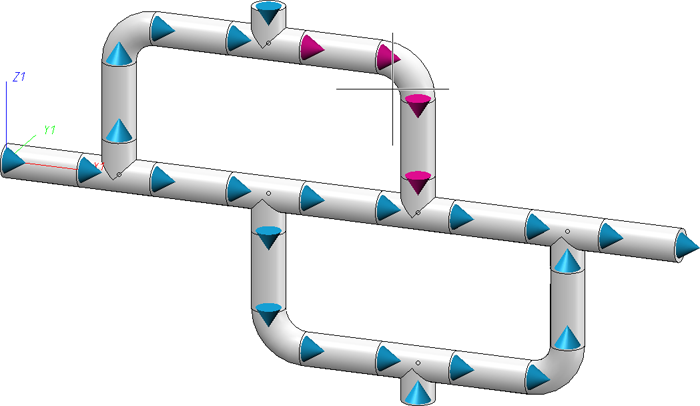
The size of the cones in the layout plan depends on the nominal diameter of the corresponding parts. The following image shows an example:
![]() Please note:
Please note:
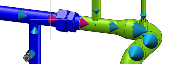
The Flow Editor does not only consider individual pipelines, but interprets connected, continuous pipelines as one, jointly editable pipeline set, as shown by the blue and the green pipeline in the image below:
Edit flow direction in the isometry
Isometry + Pipe spool drawing > Symbols > Edit flow directions
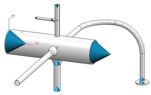
In the isometry or pipe spool drawing, too, cones indicating the flow direction will be displayed at each connecting point after selection of the function. If you move the cursor over a pipeline section, all cones belonging to this section will be highlighted in a different colour. You can then change the flow direction for the section with a simple mouse click.
In contrast to the layout plan, the cone size in the isometry is not dependent on the nominal diameter, i.e. all cone symbols have the same size.
Check plausibility of flow directions
Plant Engineering > Isometry/Pipe Spool Drawing > Assign > Check plausibility of flow directions 
Isometry + Pipe spool drawing > Symbols > Check plausibility of flow directions
Use this function to check whether the flow directions in pipelines are plausible.
If this is not the case, the corresponding pipeline section will be highlighted in the drawing, and an appropriate message will be displayed:
Example:
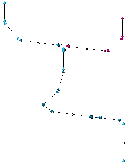
In the isometry shown below, the 4 flow direction arrows marked with red arrows were reversed with the Reverse flow direction function.
When the plausibility check for the flow direction was carried out subsequently, an error message was displayed, and the corresponding pipeline section was highlighted:
 Please note:
- If no pipeline is active when you select the function, HiCAD will prompt you to activate a pipeline.
- If several such strings should exist in a pipeline, only the first one causing an error message will be reported.
- As the flow direction can only be specified by means of the flow direction arrows, situations may occur where the flow direction cannot be determined unambiguously, causing the checking routine to fail.
- To check the flow directions in individual pipelines, you can call the function via the context menu of the pipeline: Right-click the pipeline and select Isometry + Pipe spool drawing > Check flow.

Insulation Symbols (Iso) • Isometry and Pipe Spool Drawing (PE/Iso) • Isometry and Pipe Spool Drawing Functions for the Layout Plan (PE)