Define Detail Views
Views > New > New detail view 
This function enables you to display details of the drawing enlarged in a new view, with the detail area being defined by a closed sketch.
 This function will always be applied to the active view. Please select the desired view before you call the function.
Once you have called the function, the New detail view dialogue window is displayed. Proceed as follows:
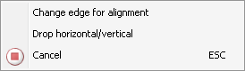
- Specify the Sketch for detail area - either by constructing a new sketch or by identifying an existing one.
- Choose the Scale for the detail view. You can set the default in the Configuration Editor at System settings > Visualization > Views with the Scale for new detail views parameter.
- Define the options for the Identification.
- Select the desired settings for the Hatching.
- Click Create to generate the view.
- Define the position of the new view.
(1) Original view with sketch, (2) Original view after defining the detail view with elliptical identification, (3) Detail view with identification, heading and hatching.
The representation of the detail view identification and the font, font height and font colour of the identification are specified in the Configuration Editor, at Drawing > Views > Ident > Details. There you can select the font, font height, font colour as well as the line colour, line type and the layer in the original view.
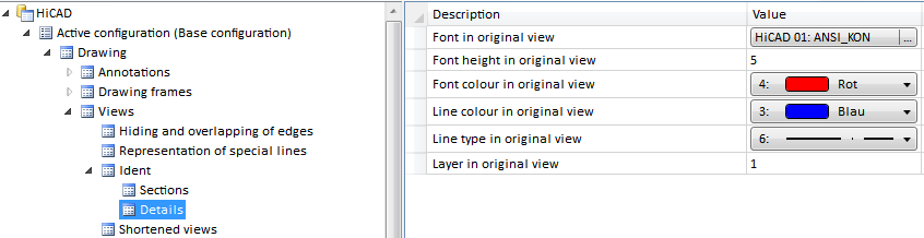
Please note that these settings do not apply to the headings (captions).
The representation of the edges can also be set via the Configuration Editor: Select Drawing > Views > Representation of special lines and choose a colour, a line type and a layer for lines, edges and borders.
Detail views are marked with the  symbol in the ICN.
![]() Please note:
Please note:
- The detail view is linked automatically to the original view.
- Detail views can also be generated from planar sectional views.
- When the section surfaces are displayed, the settings of the Hatch section + cut-out function may possibly be used.
- Note also the Properties > Hatching function in the context menu of the drawing name in the ICN. This function enables you to shade all section surfaces – irrespective of view - either according to material catalogue or by means of parallel lines.
- If you have generated the detail view with heading, it is automatically updated when the view is rotated.
- Whether a part will be taken into account in the detail view depends on its section behaviour, which can be defined with the Hatch section + cut-out function.
- Auxiliary geometries contained in the sketch will be considered for the generation of sectional and detail views. This means that edges marked as auxiliary geometries will have no influence on the geometric representation of the sketch.
- Detail views that are not up to date are indicated in the ICN by strikethrough view names and by a red cross in the drawing. For example, this is the case if you are working with detail views and transform the model after definition of the views, or if you apply Boolean operations to the model.
If you do not want the crossed-out representation in the drawing, you can change this in the Configuration Editor at System settings > Visualisation > Views, where you can deactivate the Cross out old cut outs, sectional views and detail views in graphic checkbox.
- To update detail views, choose Views > Edit > Update
 .
. - If a parameterized sketch with the purpose Create/Edit is active in a sectional view, the line end points, isolated points and the degrees of freedom of the sketch are also visualized there.
 When creating a detail view of a sectional view or of a cut-out, the current state of the sectional view or the cut-out will be copied into the detail view. If the section or the cut-out of the original view is changed afterwards, this will have no effect on the detail view. This means that the section or the cut-out needs to be changed separately if required.


Special Views (3-D) • Sectional and Detail Views (3-D) • Views (3-D)