Example: Sweep Part
The conversion to the 3-D drawing comprises three steps:
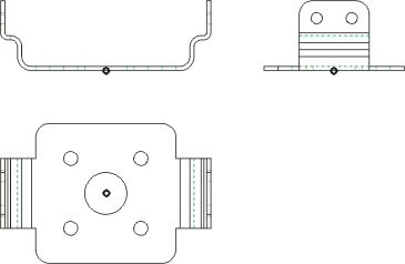
Step 1: Define views
- Load the REKO_BSP1.SZN file.
- Activate the 3-D Standard tab and select New > Extruded
 > 2-D->3-D Conversion.
 - Select the Views function from the 2-D->3-D Conversion menu.
- Draw a selection box with the corners (1) and (2) in order to define the front view.
- Specify the midpoint of the lower edge of the polyline as reference point for the view (3).
- Draw a selection box with the corners (4) and (5) in order to define the side view.
- Specify the midpoint of the lower edge as reference point for the view (6).
- Draw a selection box with the corners (7) and (8) in order to define the top view.
- Specify the centre of the circle in the middle as reference point for the view (9).
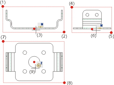
The definition of the views is now completed. HiCAD inserts isolated points into the drawing at the reference points.
 isolated points

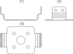
Step 2: Derive 3-D drawing
- Select the Part from Views function from the 2-D->3-D Conversion menu.
- As three views were specified during view definition, you need to define three closed polylines here:
- (1) for the front view,
- (2) for the side view and
- (3) for the top view.
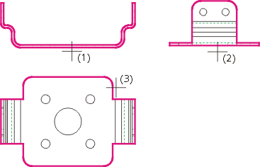
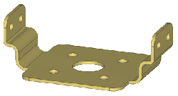
HiCAD automatically creates the corresponding 3-D model and inserts it into the drawing.
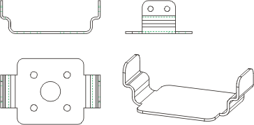
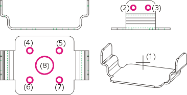
Step 3: Take over hole contours
- Select the Holes function from the 2-D->3-D Conversion menu.
- Identify the 3-D part (1).
- Identify the hole contours (2) and (3) in the side view.
- Identify the hole contours (4) - (8) in the in the top view.
- Right-click to end the selection of the hole contours.