3-D Standard > Tools > Attr... 
For assemblies, the dimensions of the parts belonging to the assembly can be used to automatically generate the attributes
- Length,
- Height and
- Width
of the assembly and enter it in the assembly attributes. All solid parts belonging to the assembly are included in the calculation, with the exception of standard and purchased parts with the insertion type Site assembly.
Excluded from the automatic calculation are structure assemblies.
Whether and when the assembly dimensions are calculated when parts are changed can be set in the Configuration Editor, namely at Modelling > Part properties > Calculate assembly dimensions.
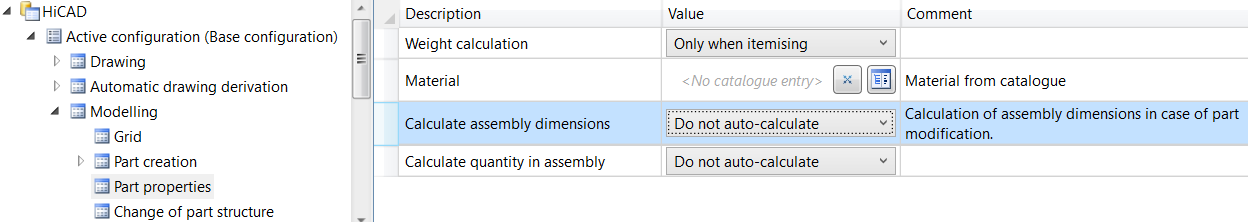
The following settings are possible there:
- Do not calculate automatically
The attributes of the assembly are not updated. This is the default setting. - Only during itemisation
The attributes are only updated during itemisation. - Always
The attributes of the assembly are updated immediately, i.e. after each change to the components or after adding further components.
To calculate the dimensions, a bounding box for the assembly is determined internally, i.e. the smallest cuboid that completely encloses the parts of the assembly to be considered.
- The orientation of the bounding box also plays a role in the calculation of the dimensions. This is determined according to the following priority:
- Alignment of the changed or newly added part, i.e. the view selected in the context menu for Parts at Properties > Part orientation.
- Alignment of the assembly main part
- Coordinate system of the assembly main part
- Coordinate system of the assembly itself
The first option that is available is used. Since each assembly has a part coordinate system, there is always a usable orientation and the dimensions can be calculated.
The assignment of coordinate system axes to the values is
- x: Length
- y: Width
- z: Height
If the part orientation (point 1 or 2) is used, length/height is derived from the front view and the width is perpendicular to it. This assignment is not configurable.
Example:
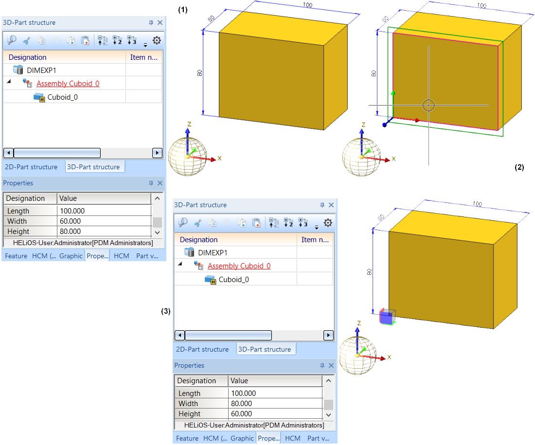
In the Configuration Editor, the parameter Calculate assembly dimensions is set to Always. In the image below, a cuboid with length 100, width 60 and height 80 was installed and then converted into an assembly. The assembly dimensions then correspond to those of the cuboid (1).
If you now change the part orientation of the cuboid (2) (top view and selection of the highlighted plane), the assembly dimensions (3) change.
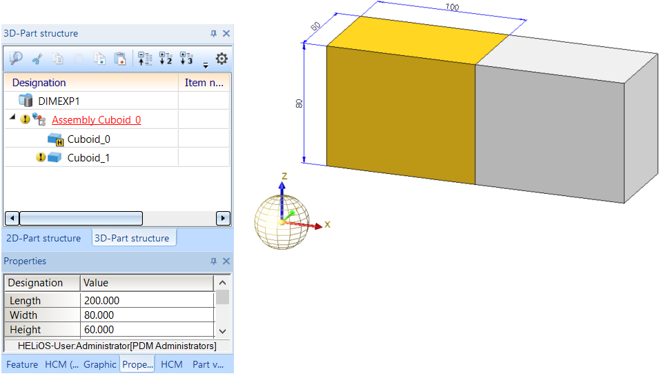
If a second cuboid is now installed as a secondary part of the assembly, the following dimensions result:
If you now change the part orientation of the 2nd cuboid as shown below, the assembly dimensions do not change initially.
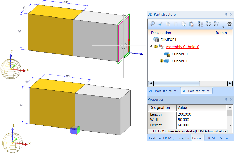
If you now convert the 2nd cuboid into an assembly main part, then the main part identification of the 1st cuboid is cancelled and the assembly dimensions change.

Non-dimension relevant parts and assemblies
Not all parts are relevant for the dimensions of assemblies. Therefore, HiCAD offers the option of marking such parts as "not relevant for dimensioning". These parts will then be ignored in all superordinate parts and assemblies when their dimensions are calculated.
To mark a part as not relevant for dimensioning, you must assign the part attribute Ignore for dimensions (Attribute name: #NDR, Attribute type: Integer). If this attribute has the value 1, it is not relevant for dimensions.
To be able to use this attribute, you must manually extend the attribute masks and/or properties windows of the ICN. Please note that this attribute is not pre-set in the masks and windows included in HiCAD's scope of delivery.
An example:
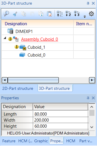
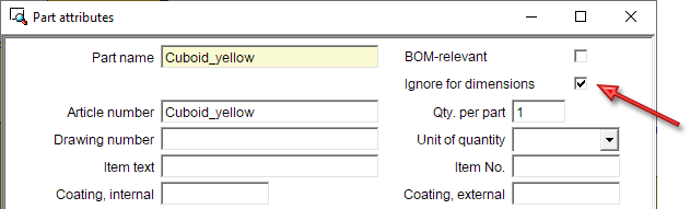
The #NDR attribute should be available in the Part attributes (3-D) dialogue window and in the corresponding Properties window of the ICN.
To do this, the files
- brw_3dteil.hdb (Properties) and
- BRW_3PART.HDX (Part attributes)
must be extended accordingly, for example like this:
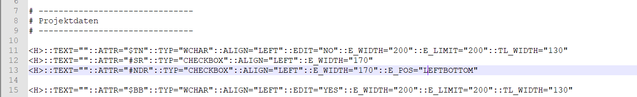
Excerpt from the HDB file:
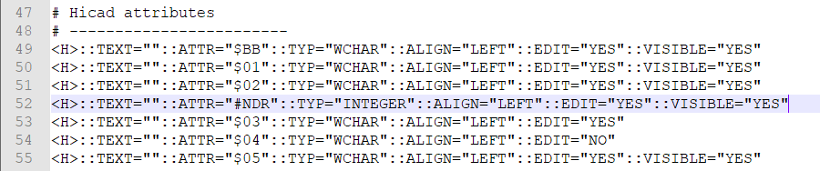
Excerpt from the HDX file:
These changes will be active when you restart HiCAD.
Let us take a look at the following example:
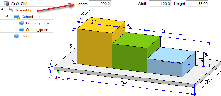
Now assign the attribute Ignore for dimensions to the part Floor.
The Floor will now no longer be considered for the dimensions of the assembly.

This is also shown in the Properties window of the ICN:
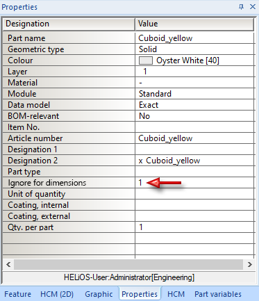
Likewise, mark the yellow cuboid s as "not relevant for dimensioning":


Information + Communication Navigator (ICN) • Part Annotation • Itemisation • Bills of Materials