Move Points
Sketch > Transform > MovePts
Use this function to move one or several points and lines of a sketch. Basically, the procedure is very similar to that of the Move, Preserve connected lines and adjust length function for sketch elements. The difference here is that not only isolated points but also individual start or end points of the sketch elements can be moved, and that the preserving of connected lines does not take place here via length adjustments, but is based on the logic of the HCM dragger. In the process, HiCAD will try to preserve the HCM constraints where possible.
When you call the function, the Move, points dialogue window will be displayed:
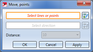
The currently active step will be highlighted with an orange frame in the dialogue window. After calling of the function these steps consist in the selection of lines or points.
Select the lines or isolated points that you wish to scale in the drawing, or use the functions of the context menu that you can open with a right-click during the selection process.
Notes on the element selection
When selecting single lines or lines in a rectangle, neighbouring points will be automatically selected, too. If an already selected line is selected again, only the single line will be selected. In order to deselect neighbouring points you have to click on them again. Full circles and full ellipsis do not have any visible seam point.
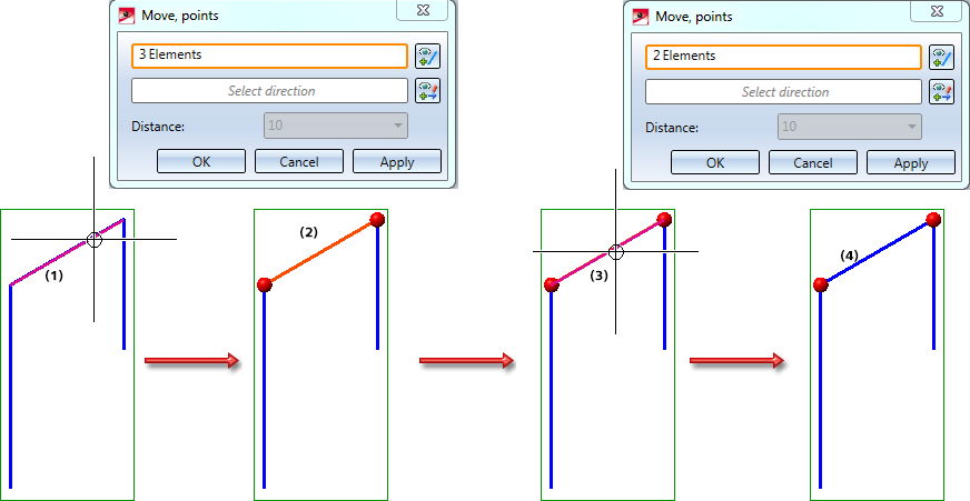
An example:
If the line (1) is selected in the image, the neighbouring points will be selected, too, i.e. 3 elements are selected (2). If the line is selected again (3), the line will disappear from the selection; however, the neighbouring points remain selected (4).
The functions in the context menu:

|
Connected lines or edges* Use this function to select all lines or edges that are connected to the next identified edge in one step. The lines and edges will be selected up to a point where a continuation would no longer be unambiguous.
|

|
Tangentially connected lines or edges* Choose this function if you also want to select all tangentially connected lines or edges when identifying the next line or edge. |

|
Lines in rectangle (CTRL+LMB)* Use this function to select lines by means of a selection rectangle. Please note that only lines of the active part will be considered. If the rectangle is drawn from the top left to the bottom right, all lines which are completely located within the rectangle will be selected. If the rectangle is drawn from the top right to the bottom left, lines only portions of which are located within the rectangle (i.e. intersect with the rectangle) will be selected as well. The selected lines will be highlighted in a different colour. You can also call the function via the keyboard. Proceed as follows:
|

|
Cancel (Esc) Cancels the function. |
*Normally, already selected lines and edges will be de-selected if you click them again.
For the above functions marked with an asterisk *, however, the following applies: If you click lines that have already been selected or if already selected lines are located in a selection, they will not be removed from the selection.
The selected elements will be highlighted in the drawing and the number of selected elements will be shown in the dialogue window:
![]()
After completion of the line selection (press middle mouse button), HiCAD automatically switches to the "Select direction" option.
![]()
Select the direction of the displacement by
- specifying the start point and the end point of the displacement vector,
- selecting an edge, or
- selecting a plane. In this case, the surface normal will be used as the displacement vector. In the case of planar sketches, the normal will be projected onto the sketch plane.
You have the additional option to right-click and open a context menu with further functions for direction specification.
|
|
Origin
|
|
|
X-axis |
|
|
Y-axis |
|
|
Z-axis |
|
|
Step back
|
|
|
Cancel
|


To change the direction, click the  icon and specify the new direction as described above.
The direction will be automatically visualized in the drawing. At the same time, HiCAD will calculate the length of the displacement vector based on the selected direction, and offers the calculated value for editing in the Distance field.
To move the selected lines/points - as shown in the preview - click OK or Apply.
When you select Apply, the dialogue window will remain open after performing the moving. Only the list of the selected elements will be deleted in the process, all other settings will be preserved and cannot be changed. In this way, further elements can be moved in the same way.
When you select OK, the dialogue window will be closed after the scaling.
When you middle-click in the drawing while the dialogue window is open, the following will happen:
- If enough value inputs have been made, the function will be executed with the current settings. The dialogue window will remain open (same as with Apply).
- If the value inputs are insufficient, HiCAD will jump to the next required selection. For instance, if you have chosen the line to be moved and then press the middle mouse button, HiCAD will jump to the selection of the direction.
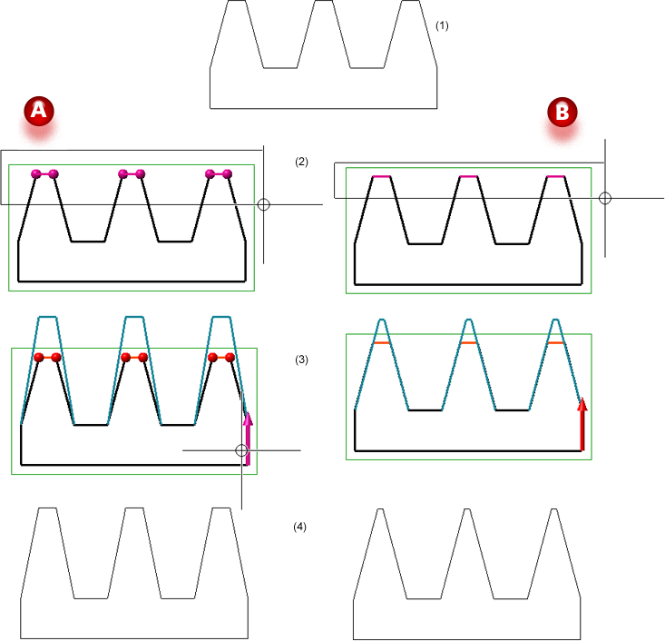
Example:
In Case A the original sketch (1) has been processes with the MovePts function; in Case B, the Move, Preserve connected lines and adjust length option has been chosen. In both cases the elements have been chosen via a rectangle (2), and the same direction (3) and the same distance has been chosen. (4) shows the results.
 Instead of clicking Apply in the dialogue window, you can also press the middle mouse button (MMB) to apply the movement.
 Please note that the selected lines and points must belong to the same sketch. Otherwise, an error message will be displayed.


Sketch Functions (3-D) • Point Functions (3-D) •Visualisation Settings