Move Points
3-D Standard > Process > MovePts 
3-D parts can be shaped by moving of points within rectangles or contours. A moving of individual points is possible, too.
The following functions are available:
|
|
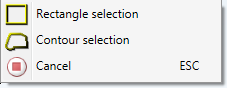
Move points in rectangle or within contour, Two 3-D points Use this function to move all points within a defined rectangle or a closed contour via specification of a displacement vector. When you call the function, the Rectangle selection will be active. You can right-click to open a context menu with further options. You can switch between rectangle and contour selection or cancel the function.
Rectangle selection Specify the 1st corner point, and then the diagonally opposite corner point. When HiCAD requests specification of the 1st corner point, you can right-click to open the context menu shown above. If a rectangle or a contour already has been specified, the transformation can be continued by clicking the middle mouse button. HiCAD will then prompt you to specify the displacement vector. When you are prompted to specify the 2nd corner point, you can click the middle mouse button to re-select the 1st corner point.
Contour selection Specify the start point of the contour, and then the subsequent corner points. When HiCAD request specification of the start point, you can right-click to open the context menu shown above. If a rectangle or a contour already has been specified, the transformation can be continued by clicking the middle mouse button. HiCAD will then prompt you to specify the displacement vector. As long as HiCAD prompts you to specify a subsequent point, you can close the contour with a right-click (provided that at least two points of the contour have been specified) , or re-start the contour specification by clicking the middle mouse button.
If the drawn rectangles or contours contain any points that do not belong to the active part, HiCAD will ask you whether only the points belonging to the active part , or all points within the rectangle/contour are to be moved. Select the desired option. You define the displacement vector by specifying two 3-D points.
(1) Rectangle, (2) Displacement vector, (3) Moving with triangulation |
Click  to open a menu with the following functions: to open a menu with the following functions: |
|

|
Move points, in edge direction As above, the displacement vector is however defined via the identification of an edge in the drawing. The direction of the displacement vector is determined by the position of the identification point. If the identification point lies to the left of the midpoint of the edge, the vector has a positive direction; if not, it has a negative direction. |

|
Move points, 2-D via 2 points As above, the displacement vector is however defined via the specification of two 2-D points. |

|
2 lines (2-D) The displacement vector is defined via the identification of two parallel 2-D graphical elements. A perpendicular (in 2-D) is dropped from the first line to the middle of the second line |

|
2 points + Length The displacement vector is defined via:
If you enter the value 0 for vector length, the displacement can also be performed dynamically with the cursor. |

|
Perpendicular Point -> Edge The displacement vector is defined via a perpendicular from a point to an edge |

|
Perpendicular Point -> Surface The displacement vector is defined via the specification of the start point and the identification of a surface. The end point of the vector is determined by a perpendicular from the start point to the surface or its enlargement. |

|
Vertical to surface The displacement vector lies on a surface normal. You can define the surface via:
The start of the vector lies on the edge end that is closer to the 1st identification point. The vector stands perpendicular on the selected surface. |

|
In dimension direction The displacement vector lies on the dimension line. |

|
Last vector Uses the displacement vector that was defined last. |

|
Last vector back Inverts the displacement vector that was defined last. |
![]() Please note:
Please note:
- HiCAD first checks whether plane surfaces are distorted by the moving of the edge. If this is the case, the message Plane surfaces are distorted. Triangulate (Y/N)? appears Choose Yes if you want the edges to be moved and the surfaces triangulated.
- If you choose the points to be moved by specifying rectangles/contours, a so-called "search solid" is defined for each specified rectangle and contour. Search solids will be displayed as previews. All points lying within these search solids will be transformed, with blind holes and technical tools also being taken into account. The search solids will also be recorded in the feature log.
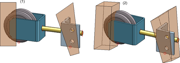
(1) Rectangle and contour, (2) Rotated view with "search solid"
In addition to the functions described here, you can also insert or delete isolated points and point designations. For example, you can use two isolated points for the definition of rotation axes. You can access the appropriate functions via 3-D Standard > Tools > New point.


Model and Process Parts (3-D) • Edge Functions (3-D) • Surface Functions (3-D)