Settings: Bore Tables
3-D Dimensioning + Text > Tools > Extras  > Tables, Bore table settings
You use this function to define text parameters for bore tables. Select the desired parameters on the corresponding tabs:
Once you have made the desired settings, click OK to exit the window.
![]() If you want the settings also to apply to existing tabular dimensions,
use the Update bore table function.
If you want the settings also to apply to existing tabular dimensions,
use the Update bore table function.
General Tab
- Frame, Line colour, Font
- Decimal places
- Point symbol, Processing symbol
If you want to use point and processing symbols of the HiCAD symbol table, enter the relevant symbol number.
- Rows per table, Distance between tables
You can also divide tables according to a certain number of rows. To do this, specify the number of rows per table and then the distance of the tables from one another. If you do not want the table to be divided, set the Rows per Table field to 0.
- Title and Footer
Here, you can assign a title and a footer text to the table. These texts are displayed above (title) or below the table.
- Annotation distance, Annotation angle
The values specified in the drawing are marked accordingly. You define the position of this annotation by specifying annotation spacing and angle.
- Annotation to centre
Activate the checkbox if you want the annotation of the bore table to be placed in the centre of the corresponding standard processings.
![]() You can save the table settings. To do this, enter the file name in
the Favourites field and click the diskette symbol.
The file is saved with the file name extension .MT3 (.MT2 in 2-D) in the
HiCAD SYS directory.
You can save the table settings. To do this, enter the file name in
the Favourites field and click the diskette symbol.
The file is saved with the file name extension .MT3 (.MT2 in 2-D) in the
HiCAD SYS directory.
Columns Tab
On this tab, you define the columns that you want the table to consist of. The column headers are defined on the left, the column contents on the right.
To insert a column, right-click an empty row and choose Insert. To remove a column, right-click the corresponding rows of the tab and choose Remove.
To define or change the column contents, double-click the mouse in the relevant row under Contents. Next, choose the desired entry in the list box. To define the corresponding column header, double-click to activate the corresponding row under Heading and enter the header.
You use the ![]() and
and ![]() keys to change the order
of the columns.
keys to change the order
of the columns.
Sorting Tab
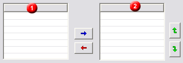
On this tab, you define the table's sort criteria. To copy a sort criterion
from the Default (1) column, select the relevant entry and click the
![]() arrow key. Similarly,
use the
arrow key. Similarly,
use the ![]() key to remove the sort criteria (2).
key to remove the sort criteria (2).

Use the ![]() and
and ![]() .keys to change the sort
order.
.keys to change the sort
order.
If the Activate sorting checkbox is deactivated, the sorting defined in the upper area of the window will be disabled, and the table will be rearranged unsorted after closing of the window.
Filter Tab
You can filter bore tables according to different criteria.
First choose the desired setting in the list box.
- Processings are visible in plane
Only the standard processings visible in the selected plane are selected.
- Centre is element of plane
Only standard processings whose centre lies in the selected plane are taken into account.
- Check direction
Only processes in plane direction are taken into account.
Then choose the processes to which you want the selected list box setting to apply by activating the corresponding checkbox.
Other Tab
- Point designation
Specifies the annotation of the standard processings taken into account during bore table creation
- Increment
If this box is active, a (consecutive) different code letter is used in numbering for additional tables for different levels. If, for example, you have created a table for a level with numbering W1, W2 etc., then the next table for a different level uses the numbering X1, X2 … .
- Bore diameter, Thread diameter
Bore and thread diameters can, if required, be displayed differently in the table. For example, you can place an M before thread diameters.
- Use diameter if catalogue designation missing
If this checkbox is activated, the diameter character, followed by the bore diameter, is shown for free bores without assigned catalogue designation in the Designation column.

