Sketching Tool for Planar Sketches
Sketch technology is a quick drawing mode for polylines. With this technology, construction is made easier by the fact that HiCAD automatically fades in auxiliary lines along a predefined grid, starting from the last point of a polyline, and displays the relevant angles, distances and radiuses at the cursor. On this grid, you can then click the mouse to define the direction and length of a line by means of corresponding cursor movements. You can preset the precision of this grid fineness in SKIZZTEC.DAT. It changes automatically, depending on the screen zoom.
Sketch technology has a context menu which you use the right mouse button to activate during sketching. The functions of this menu enable you to do the following:
- change the grid mode,
- switch between absolute and relative angle display and
- insert arcs into the sketch.
During sketching you can also call the numerical point options via shortcuts. Distances, too, can be entered via the keyboard: Press the space bar, enter the distance(s) and confirm with OK. For point options with angles place the cursor in such a way that the correct angle is shown before pressing the space bar.
![]() Note on the Autopilot:
Note on the Autopilot:
When sketching lines, additional options are available for point specification via the Autopilot:
|
|
Is displayed if the x-coordinate of the current cursor position is identical to the x-coordinate of another point of the active part. |
|
|
Is displayed if the y-coordinate of the current cursor position is identical to the y-coordinate of another point of the active part. |
|
|
Is displayed if both the x- and y-coordinates of the current cursor position are identical to the x- and y-coordinates of another point of the active part. |


Together with the display of the point option, an auxiliary line is also displayed on the point with identical x- or y-coordinate. All points of the active part and the origin of the sketch or the 2-D drawing are taken into account.
Furthermore, depending on the cursor position, both the point options
 (O) Online to edge through point as well as
 (F) Perpendicular base point
is displayed when the cursor is close to a straight line. For circles, the options (Z) Centre, (F) Perpendicular base point and (T) Tangetial point are also displayed.
 For 3-D sketches a 3-D Sketching Tool is available.

Grid modes and angles
Sketch technology has various grid modes that can be selected from the context menu (click RMB). In addition, you can switch between absolute and relative angle display.
|
Function |
||
|---|---|---|
|
|
Angle + Distance |
In this mode – HiCAD default setting – the angle and the distance from the last point are displayed. To define the next point, place the cursor at the desired position and left-click to apply it. Alternatively, you can also enter the distance via the keyboard. Place the cursor so that the correct angle is displayed, and press the space bar. Enter the desired distance and press OK. |
|
|
Direction + Distance |
Initially, only the angle to the preceding point is displayed here. Left-click to apply the displayed angle, or press the space bar and enter the angle via the keyboard. HiCAD then displays an appropriate auxiliary line. Next, the distance is displayed at the cursor. It is marked off, starting from the last point on the angle auxiliary line. Left-click to apply the distance or, after pressing the space bar, enter it via the keyboard. This mode only ever applies to one input; afterwards, the grid mode predefined in SKIZZTEC.DAT becomes active again. |
|
|
XY-grid |
The X- and Y-distance from the last point is displayed. To define the next point, place the cursor at the desired position and left-click to apply it. Alternatively, you can also enter the values via the keyboard. To do this, press the space bar and, in the input window, enter the X- and Y-distance, separated by a space or a comma, e.g. 100 50. Click OK to exit the input window. |
|
|
Absolute angle |
In the case of the absolute display, the angle refers to the x-axis of the coordinate system. If the absolute angle display is active, the angle is displayed in red at the cursor. |
|
|
Relative angle |
In the case of the relative angle display, the angle refers to the last line. If this display is active, the angle is displayed in cyan. |


![]() Please note:
Please note:
- You can use the +/- keys to influence the precision of the distance display.
- When entering distances via the keyboard, you can enter the character # to cause the last two lines to be closed and form a parallelogram.
Insert arcs
Use the Arc  function to insert arcs into a polyline using sketch technology. After selecting the function, an auxiliary circle will be created tangentially to the last line, and the radius will be shown at the cursor. The click position of the cursor will also be evaluated.
Apply the radius with a left click, or press the space key and enter the value via the keyboard.
Please note:
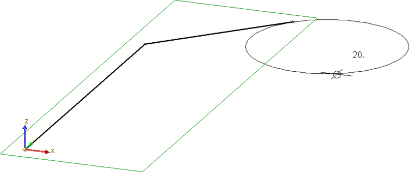
If you click in the 1st or 2nd quadrant of the arc, the arc will be attached tangentially in the direction of the last created line element. If you click in the 3rd or 4th quadrant while determining the radius, the arc will be attached tangentially in the opposite direction of the last created line element, i.e. an arc that is complementary to the preview.
This means that during radius determination, the cursor must already be located on the circle side the circular path of which you want to run along!
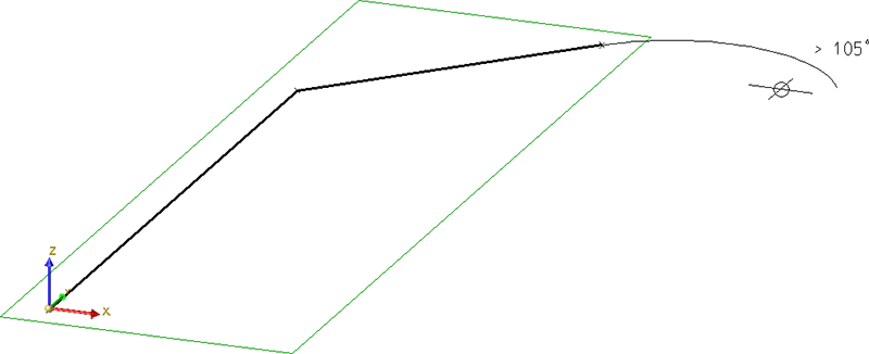
After radius determination, the arc aperture angle will be shown at the cursor. You can change this angle by moving the cursor. Apply the desired angle with a left click, or press the space key and enter the value via the keyboard.
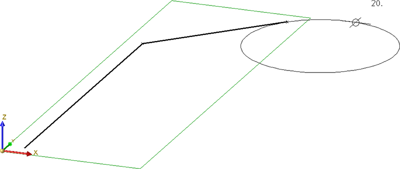
Example:
Let us assume that you want to insert an arc at the marked point. The marked point also determines the position of the quadrants that play an important role for the creation of the arc.
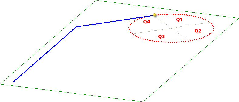
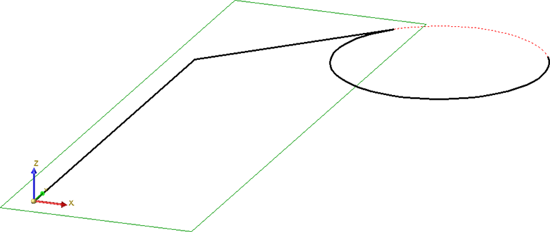
Radius determination in the 1st quadrant
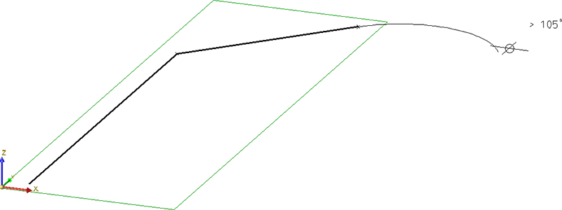
Displayed arc aperture angle
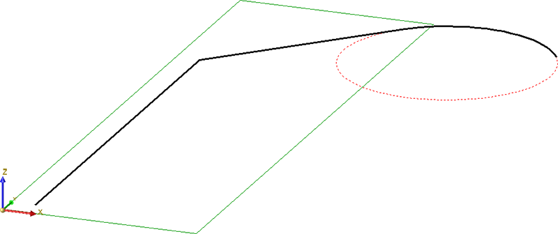
Created arc
For comparison:
![]() The arc will also be attached tangentially to a previously created arc.
The arc will also be attached tangentially to a previously created arc.

Working with Sketches (3-D) • Sketch Functions (3-D) • Sketching Tool for 3-D Sketches