Insert Form/Positional Tolerances
3-D Dimensioning + Text > Surface/Edge > Form/Pos

Once you have called the function, the Form/Positional Tolerances dialogue window is displayed,enabling you to set the desired parameters for the tolerances. Once you have clicked OK to exit the dialogue window, the insertion of the tolerance begins.
Load/Save as favourite
You can save the current settings in the Form/Positional Tolerances window as an FPT file and subsequently reload them at any time.
- To save the current settings in a new file, enter the file name and then click the diskette symbol. The file is saved under the specified name with the extension .FPT in the HiCAD SYS directory.
- To load an existing file, simply select the file in the list box.
- To change an existing file, choose the file name from the list box, make the desired changes and then click the diskette symbol.
Select leader line
The following options are available for leader lines:
|
|
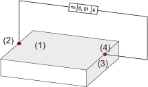
Tolerance with element (leader line with angle) |
|
|
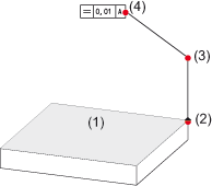
Tolerance with element and reference (twice-angled leader line) |
|
|
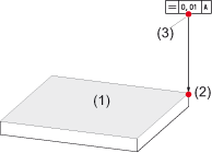
Tolerance with reference (perpendicular leader line without angle) |
Choose the desired leader line type by activating the corresponding symbol. The symbol is then highlighted. In the case of reference lines with a bend, you can also choose how you want the symbol line to be drawn. In the case of a twice-angled reference line, this option can be selected separately for both lines.
![]()
Symbols, tolerance values and letters
The geometrical tolerances are specified in a rectangular frame - the tolerance frame. It consists of two or more compartments containing the symbol for the feature to be toleranced, the tolerance value, the letter for datums..
|
|
Parallelity |
|
Straightness |
|
Cylinder Form |
|
Section of a |
|
|
Planarity |
|
Rectangularity |
|
Symmetry |
|
Section of a |
|
|
Runout |
|
Roundness |
|
Total runout |
|
|
|
|
Inclination |
|
Concentricity |
|
Position |
|
|
You can select the toleranced property quite simply in the list box. In the other fields, you can define the tolerance values and letters.
You can additionally select the ![]() Maximum Material Condition or the
Maximum Material Condition or the ![]() Projected (Upstream) Tolerance Zone ID for any value or letter. You can select the
ID directly in the list box. You can place the diameter symbol
Projected (Upstream) Tolerance Zone ID for any value or letter. You can select the
ID directly in the list box. You can place the diameter symbol ![]() or the
or the ![]() character as a plus/ minus sign in front of the values in the input field.
}
character as a plus/ minus sign in front of the values in the input field.
}
Enter tolerances
Once you have selected all the settings in the Form/Positional Tolerances window, click OK to exit the window. The
ensuing dialogue depends on the selected leader line option
|
|
|
|
|
|
|
|
|

Form/Positional Tolerances (3-D) • Dimensioning (3-D) • Text and Annotation (3-D)


