Angle Dimensioning
3-D Dimensioning + Text > Angle
With the functions under Individual dimensionsand Angle you can create angular dimensions as individual dimensions or structure dimensions.
- Activate the part to which the dimensions will be assigned.
- Select the desired dimensioning function.
- Determine the base points by selecting any points, edges or surfaces - depending on the settings in the Element type selection dialogue window (see also Dimensioning - Procedure).
- Determine the position of the dimension by dropping it. Via right-clicking theDimensioning, Move menu can be activated.
- Determine the subsequent base points for the structure dimensions or end the function by pressing the middle mouse button.

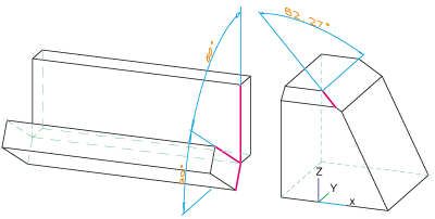
Left: Angular dimensions (chain), Right: Angular dimensions, leg - y-axis
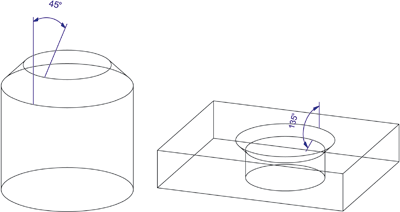
Chamfer dimensions for chamfered bores or cylinders can also be created via angular dimensionings. In the example below, the Angular dimensions ... - Z-Axis  function was used for this purpose.

Function overview
|
Under 3-D Dimensioning + Text > Individual dimensions |
|
|
|
dimensions the angle between two edges. Identify both legs (exceptions arc) and determine the position of the dimension line. If an arc is to be dimensioned the identification of the arc and the subsequent definition of the dimension line position. However, in this case no snap point may be activated when identifying the arc! |
|
|
Angular dimension, via points/edges/surfaces dimensions the angle between 2 edges or surfaces. The edge selection can take place via direct identification of the edge, or by specifying of two points. |
|
|
Angular dimension, X-axis dimensions the angle between an edge and the X-axis. |
|
|
Angular dimension, Y-axis dimensions the angle between an edge and the Y-axis. |
|
|
Angular dimension, Z-axis dimensions the angle between an edge and the Z-axis. |
|
|
Angular dimension, with axis dimensions the angle between an edge and an arbitrary axis. |
|
Under 3-D Dimensioning + Text > Angle |
|
|
|
Chain dimension* creates a chain dimension, i.e. a group of angular dimensions in which two consecutive angular dimensions share a leg. |
|
|
Parallel dimension* creates a parallel dimension, i.e. a group of angular dimensions in which all sub-dimensions have the same start leg and the dimension lines of the individual sub-dimensions have a static distance in between each other. |
|
|
Running dimension* Creates running dimensions, i.e. a group of angular dimensions in which all sub- dimensions refer to the same start side. The dimension figures are automatically placed at the end of each dimension unit, perpendicular to the dimension line. |
* If you choose a point as the base point for a structure dimension, the start/end point of the leg needs to be determined afterwards.
 Please note:
- If the base points of an angular dimension determined by the identified legs are not parallel to the current screen plane, HiCAD will display the following error message:

If this message is displayed, check the dimension figure.
- For new dimensions the current Dimensioning parameter settings will be considered. It has to be taken into consideration that the dimensions - depending on the settings in the System tab - will be projected onto the active processing plane.
-
Please also read the information under Dimensioning - Procedure and Dimensioning - Element Type Selection.


