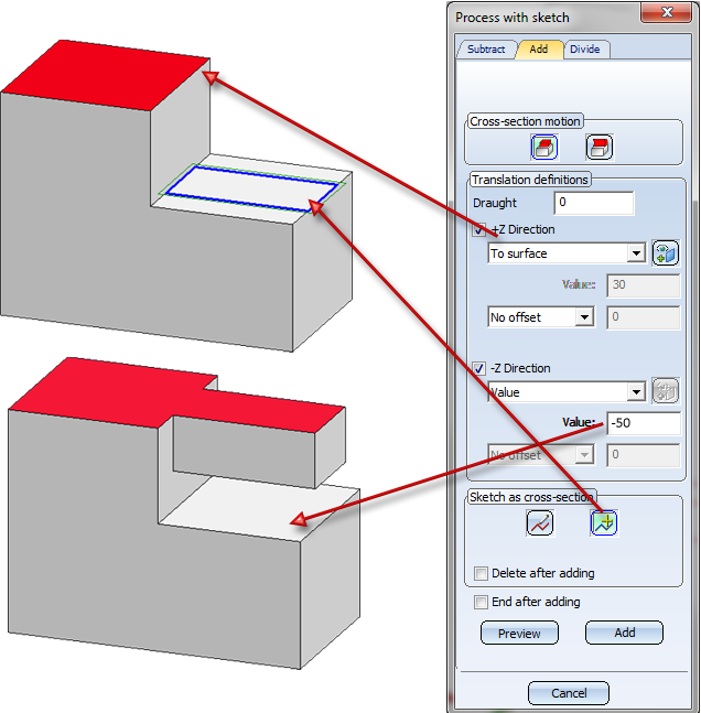
The "Process with Sketch" Dialogue Window
3-D Standard > Process with sketch
You can use the Process, with sketch dialogue window to make all the settings required for subtracting, creating bores, adding and dividing.
Tabs
The Process, with sketch dialogue window consists of three tabs :
- Subtract
You use a 3-D sketch to insert a subtraction with translation or rotation or a bore. You select the function beneathCross-section motion:
|
|
|
|
|
|
|
|
- Add
You use a 3-D sketch to add bodies to the active part through translation or rotation.
|
|
|
|
|
- Divide
The active part is cut into two parts. The cut is determined by means of a 3-D sketch.
![]() Please note:
Please note:
- In all tabs, the settings and values that were last used become the default setting.
- The functions of the tabs are identical to the functions of the Process part, with sketch context menu.

General Options
The following options and settings are generally identical for all tabs.
- Include sub-parts
If this checkbox is active, the sub-parts of the active part are also taken into account when applying subtractions, bores and divisions.
- Draught
Specifies the angle of inclination of a so-called draught (form-inclination). The position of the draught is influenced by the plus/minus sign.
- Select sketch

You use this function to take over an existing sketch for processing.
- New sketch

You use this function to create a new sketch. If you select this function, the Sketch tab is activated. Please note that the settings of the Novice configuration are taken into account here.
- Subtract in open sketch.....
You can also crop areas of the active part when applying subtractions and bores. In this case, the 3-D sketch is used as a cut line. If you also want to use open sketches as cut lines, you must activate the checkbox. HiCAD then asks you within the function dialogue to identify the side of the part that you want to be cropped.
- Delete after ...
The sketch is automatically deleted once the corresponding function has been executed.
- End after ...
The dialogue window is automatically closed once the corresponding function has been executed.
The buttons:
A processing preview is displayed. With dynamic height determination, now drag the cursor to the desired position and press the left mouse button.
- Add/Subtract etc.
The processing is applied without preview.
- Apply
The part is applied as displayed in the preview (only active in preview mode).
Subtract / Add with Translation
The depth of a material subtraction can be marked off in positive or negative Z-direction. The depth can also be specified dynamically with the cursor.
 +Z-direction
The depth will be marked off in positive Z-direction. The following options for the specification of the subtraction depth can be chosen from the listbox:
- Value
This value determines the depth of the subtraction. - Dynamic
The depth of the subtraction will be determined dynamically using the cursor. Drag the cursor to the required position and click. The depth specified in this way will be shown and can be modified if desired.
- Through
The subtraction will go completely through the part. - To next exit surface (or entry surface)
The subtraction will be automatically lengthened in positive Z-direction up to the next continuous surface of the active part. If the subtraction is too large, HiCAD will automatically attempt to perform a trimming to the surface. - To point
The subtraction will be automatically lengthened up to a specific point in positive Z-direction.
Click the Select point symbol and specify the desired point.
 - To surface
The subtraction will be lengthened in positive Z-direction up to a specific surface.
Click the Select surface symbol and specify the surface.
 - To part
The subtraction will be lengthened in positive Z-direction up to a specific part. Please note that the bottom/top surface of the body to be subtracted/added must completely lie in the surface of the selected part. Otherwise the action cannot be performed.
An example:
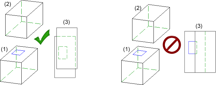
(1) Original part with sketch, (2) Up to part, (3) Top view. Left: Subtraction / addition possible, Right: Action not possible
Click the Select part  symbol and identify the part.
When you select the options To point, To surface and To part, you can additionally specify an offset. Here you can choose between a "real offset" and a mere displacement parallel to the direction of the translation. Please note that there will be no difference between offset and displacement if the surface is planar.
Example: Offset and displacement
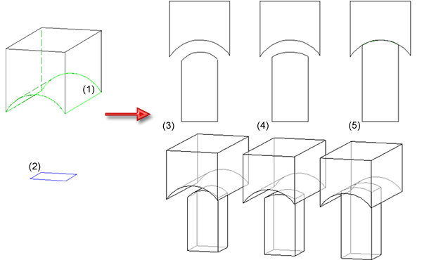
Right: (1) Original with selected surface (up to surface), (2) Selected sketch
Top left - Front view: (3) with offset, (4) with displacement, (5) without offset - Bottom left: Axonometry
-Z-direction
The depth of a material subtraction can be marked off in negative Z-direction. The same options as for the +Z-direction functions are available.
![]() Please note:
Please note:
- The +Z-direction and -Z-direction options can be active at the same time. You can therefore mark off the depth for both simultaneously.
-
If you want to perform an addition in +Z-direction, with the addition not beginning directly on the selected sketch, but with a certain distance from it, this can be achieved by specifying an additional negative value in -Z-direction.
- As with the depth of subtractions, you can specify the height of added bodies.
- You proceed likewise with additions via rotation.
 Important:
- If the feature with the new feature (To point, To surface and To part) is recalculated in a HiCAD Version older than 1902, the addition/subtraction will not be created, i.e. the geometry of the part will change.
- If a drawing in which the new feature options (To point, To surface and To part) had been used is sved in a HiCAD version older than 1902, these information will be lost; if the drawing will be loaded again in Version 1902, and a feature recalculation is performed, the additions/subtractions cannot be created any more, i.e. the geometry of the part will change. This will happen irrespective of whether a recalculation has been performed in the older version or not.
Using the optionsTo point, To surface and To part) may result in a loss of data if you load the corresponding drawings with a HiCAD version older than 2014, SP2.
Example - Subtract, with translation (3-D)
Example - Subtract, with translation + depth (3-D)
Subtract / Add with Rotation
The following options are available for subtracting with rotation:
![]() Segment
Segment
The subtraction is created by a partial rotation. You have the following options to define the rotation angle:
![]() Dynamic
Dynamic
The rotation angle is defined dynamically with the cursor.
Start/End angle
The start angle and end angle for rotation are specified explicitly.
![]() Segment
Segment
The subtraction is created by a full rotation.
![]() Select rotation axis
Select rotation axis
Prompts you to identify a rotation axis.
![]() Similar options are also available for adding via rotation.
Similar options are also available for adding via rotation.

Working with Sketches (3-D) • Process Part with Sketch (3-D) • Model and Process Parts (3-D)