
Project: HiCAD Steel Engineering
The following steps are required to derive 3-D series beams from 2-D parts:
1st case: The 2-D part already exists
If the 2-D part for the cross-section of the series beam already exists, you will need to ensure that it complies with the conventions for series parts.
If, therefore, the 2-D part contains contours for exact and simple representation or elements that you do not want to be taken into account during beam creation, you will need to create corresponding sub-parts with the name EXACT, SIMPLE or 2-D.
To insert an existing 2-D part into the drawing and to process it, use the functions provided by the Insert Part function group on the Drawing tab.
Next, perform the required processing steps and make the necessary changes to the part structure.
2nd case: The 2-D part does not yet exist.
In this case, you create a new 2-D main part and then draw the beam cross-section using the 2-D functions. Note, however, that the beam cross-section is only allowed to have one outer and one inner contour. The position of the beam axis is determined by the position of the 2-D cross-section in relation to the origin of the 2-D coordinate system. If necessary, therefore, before saving, shift the beam cross-section so that the desired point for the axis lies in the origin of the 2-D coordinate system, i.e. Absolute (0,0)
You also need to comply with the conventions in respect of the part structure here. If your part contains only the elements required for the beam and if you do not want to distinguish between exact and simple representation, you do not, of course, need to create the above-mentioned sub-parts.
Example of a series beam (FIG file basis) in simplified and exact representation: (1) The 2-D contours lie exactly on top of one another in the drawing.
Tip:
The 2-D part for the
beam contour can also consist of several assemblies containing SIMPLE,
EXACT etc. The following figure shows a case
of this type. 
2-D part with (1) Notch contour (CUTOUT) and (2) Points for
glass fitting (GLASS)
You can assign certain attributes directly to each 2-D series cross-section. Series beams, and also their sub-parts, assume all part properties (including part type and BOM-relevance) from the generating 2-D series cross-section.
Choose Steel Engineering > Further functions > Settings  > Series cross-sections, Assign attributes
  to assign the desired attributes (e.g. material, BOM-relevance, Part type...) to a 2-D series cross-section.
Tip:
In HiCAD, a usage is automatically assigned to standard beams and many other 3-D objects. This classification allows, among other things, the creation of usage-dependent workshop drawings, i.e. it is possible to individually specify views or dimensioning rules for the different usages.
For series beams that are based on 2-D series cross-sections, the assigning of a usage is not possible; however, own configurations for drawing derivations can also be defined and used for series beams. This is made possible by a suitable part type called, e.g. Series in the Configuration Editor. When assigning attributes to the individual cross-sections, this part type will be entered into the Part type field. in this way, the 3-D series beams, too, will obtain this attribute upon their insertion. When generating the workshop drawing, the configuration assigned to the part type Series can be used for series beams.
The exact procedure is described in the Usage Assignment for Series Beams topic.
After successful creation and attribute assignment save the 2-D series cross-section - either via Explorer or directly to the catalogue for series beams.
Save via Explorer
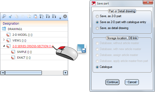
In the ICN, right-click on the 2-D main part and select Save part  .
.
Activate the desired option in the dialogue beneath Storage location, DB link and click Continue to save the part as .FGA file.
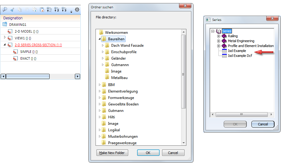
Save as catalogue part
To save the 2-D main part with the series cross-section directly to the BAUREIHEN (=SERIES) catalogue, choose Steel Engineering > Further functions > Settings > Series cross-sections, Save as catalogue part  .
.
Proceed as follows:
Use the functions in the New function group of the Steel Engineering tab to insert series beams:
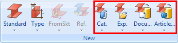

Series Beams (3-D SE) • Insert Beams (3-D SE) • Steel Engineering Functions
|
© Copyright 1994-2019, ISD Software und Systeme GmbH |