Project: HiCAD Steel Engineering
Series Beams
Steel Engineering > New
This HiCAD function enables you to insert beams of user-defined series.
A series beam can be derived from:
- a 3-D part with one or several sketches (.KRA)
- a normal 2-D part
(.FIG),
- a 2-D HCM file (.DCF)
or
- a 2-D variant (earlier
HiCAD version, .FIV)

Series beams from 3-D parts with sketches
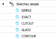
A sketch-based series beam can consist of one single part (e.g. a Steel Engineering beam) or of several parts (e.g. a window frame with inner and outer element and seals).
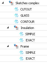
The associated model of sketches consists of an assembly or a dummy part containing either directly the sketches with the contours for simple and exact representation of the beam, or, in case of multi-part beams, further assemblies or dummy parts with the corresponding sketches. These may be arbitrarily deeply nested.
These sketches must have the name SIMPLE for the simplified representation and EXACT for the exact representation, and must have no further sub-parts.
Furthermore, the following rules apply:
- Notch contours must be defined in a sketch called CUTOUT.
- Point for glass pane insertion must be defined in a sketch called GLASS.
- If you want to use the contour representation for series beams, an additional sketch called CONTOUR that contains the simplified contour of the entire beam must exist.
- The parts GLASS, CUTOUT and CONTOUR must be on the uppermost level, and not in assemblies or dummy parts on lower levels.
- Assign a material, and, if required, further attributes to the uppermost assembly or the assemblies containing the sketches called SIMPLE and EXACT (in the above example these are the assemblies called Insulation and Frame). Set the BOM-relevance to Yes, to ensure that the part will be considered for bills of materials and itemisation.
- Move the relevant assembly in such a way that its centroid coincides with the origin of the coordinate system. There, the beam axis will be placed when the beam is inserted.
- If a beam consists of several parts, but is to be interpreted as one single part in BOMs and workshop drawings, you can set the BOM-relevance of the assemblies of the individual parts to No, with the exception of the uppermost assembly, where you set them to Yes.
- Currently in insertion of sketch-based series beams is only possible if the part has been manually entered in the catalogue. Alternatively, you can also use a series beam from 2-D parts. For these, convenient Save functions are available.
- Save the part via Drawing > Save/Reference > Reference part, Save, Detail drawing and with the Save as part option as a .KRA file to the sub-folder Kataloge(Catalogues) of your HiCAD installation. Then, enter the new beam manually via the Catalogue Editor to a table in the path Factory standards > Series. After this, you can insert the new beam via Steel Engineering > New > Insert series, via catalogue.
Series beams from 2-D parts
Conventions for
Series Figures
A 2-D series figure can consist of an individual part or an assembly. An assembly can contain both the contours for simple and
exact representation and 2-D elements which you do not want to be included in the beam generation.
It is important that the following rules are observed:
- Elements which
are to be excluded from the creation of the 3-D beam can be grouped in a sub-part
with the name 2-D.
- Notch contours must
be located in a sub-part CUTOUT.
- Points for glass insertion must be defined in a sub-part with the name GLASS.
- If you want to use the contour representation for series beams, a part with the name CONTOUR containing the simplified contour of the complete beam.
- If the 2-D model consists of several main parts, the parts GLASS, CUTOUT,and CONTOUR must not be located on the same level as the parts SIMPLE and EXACT, but on the same level as the the main parts.
- Assign to the sub-parts EXACT and SIMPLE a material and, if required, further attributes. Set the BOM-relevance to YES. These settings, as well as the colour and the line types, will be applied when the 3-D Steel Engineering beam is created. A material should be assigned to the part in any case. The BOM-relevance is particularly important, as only a BOM-relevant series beam will actually appear in the BOM and will be automatically itemised. The easiest way to assign these properties is to choose Steel Engineering > Further functions > Settings
 > Series cross-section - Assign attributes.
- The centroid of the 2-D part should be located in the absolute zero point. There, the centroidal axis will appear later.
 Important:
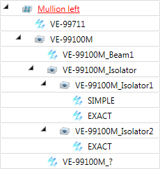
In practice, individual beams in series beam groups can consist of several different cross sections.These can also have different materials, which means that they must be hatched correctly in sectional views. In BOMs and in workshop drawings, however, such beams are always interpreted as 1 part. Therefore, HiCAD also supports series beam groups with individual beams consisting of several, BOM-irrelevant cross-sections. The image below shows an example:
 Please note:
- If the 2-D series part contains the sub-parts EXACT and SIMPLE, a feature recalculation will be performed when you switch between simple and exact representation for the corresponding 3-D series beam. If the 2-D series part contains the sub-part CONTOUR, the view list will be changed if the corresponding 3-D series beam is e displayed in contour representation, i.e. the part CONTOUR will be shown, and the other representation will be hidden.
- To process a series
beam, you must identify the entire beam. The following options are available
for this:
- choosing the Select beam main part function from the context menu for beams (RMB on Beam), or
- selecting the series
beam via the beam axis, or
- activating the
Group snap identification mode in the transparent toolbar. The group snap mode is active if the
 symbol is displayed on the transparent toolbar. To switch to group snap, multiple clicking of the icon may be required.

- For series beams you can specify in the Configuration Editor at Steel Engineering > Representation > Representation of series beams whether the edge colour of the 2-D series part should be determined by the edge colour of the figure or by the default edge colour of the drawing. The default setting is Take colour from 2-D part
 .
.

Fitting
Options for Beams (3-D SE) • Insert Beams
(3-D SE) • Steel Engineering
Functions • Series Cross-Sections
|
© Copyright 1994-2019, ISD Software und Systeme GmbH
Version 2402 - HiCAD Steel Engineering
Date: 04/11/2019
|
> Feedback on this topic
|