Project: HiCAD Steel Engineering
"Civil Engineering functions" docking window > Steel Engineering > Connections > Front side to web/flange side > Front plate > Front Plate Connection to Web/Flange (2320)
Use this function to connect 2 beams via a bolted front plate connection. The connection can be made to the web or to the flange - with or without filler plates. Depending on the fitting situation, the connected beam will be automatically notched appropriately. Furthermore, weld seams can also be directly inserted and annotated.
The connection can be a user-defined connection or configured via predefined DAST tables supplied with HiCAD.
Supported beam and profile types are I-beams, U-beams, T-beams, Z-profiles, pipes and hollow profiles.
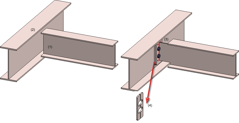
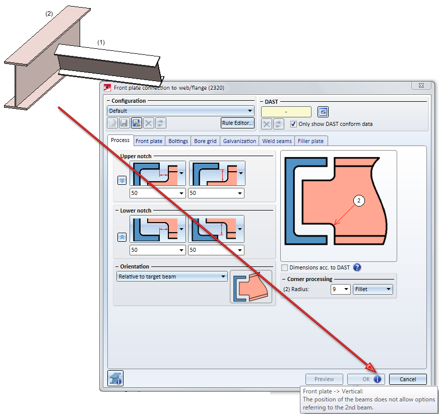
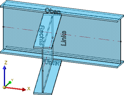
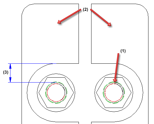
(1) Beam to be connected, (2) Target beam to which connection is to be made, (3) Created connection, (4) with filler plates
Proceed as follows:
The dialogue window for the front plate connection will be displayed. The configuration of the front plate connection takes place via the tabs of this dialogue window.
Click the Preview button to show a preview of the connection according to the currently entered data. If you want to modify the data, change them and click Preview again to update the preview. Clicking OK inserts the connection according to the current data and closes the dialogue window. Clicking Cancel closes the window without inserting the connection or applying the changes.
Symbols:
|
|
Selected parts Click on this symbol to show information on the previously identified beams, such as the type of the beam, the material, the dimensions, etc. Value inputs and changes are not possible here.
|
|
|
Invert concerned connection values horizontally Click on this symbol to switch specified values horizontally, i.e. right and left. For instance, this can be done for
|
|
|
Invert concerned connection values vertically Click on this symbol to switch specified values vertically, i.e. top and bottom. For instance, this can be done for
|
![]() Please note:
Please note:
 s
s
 Important:
 on the OK button. When you move your cursor over this symbol, further information will be provided.
The configurations of the front plate connections can be saved, which enables you to access your individual configurations at any time afterwards.
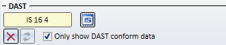
The insertion of the front plate connection can take place as a user-defined connection or according to DAST tables. The input/selection fields are initialised with values, depending on the selected configuration or the selected connection type, and can be modified if desired.
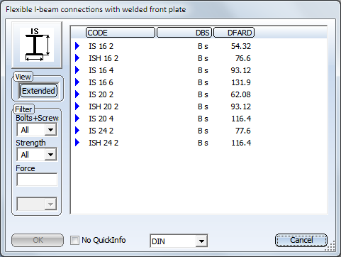
The data for the typified Steel Engineering connections according to DSTV/DAST are in stored in tables in HiCAD: To apply the data for the related parts such as plates, screws etc. from these tables, select the connection type first.
To do this, click the  symbol and select the desired connection in the displayed dialogue window.
Click the Extended button to show more data of the possible connections. You can set one or several filters (Bolts+Screws, Strength...) to limit the selection options. Select the desired option and close the window with OK. The designation of the selected DAST connection will then be shown in the input field.
After the selection of the DAST connection, the contents of the tabs will be adjusted accordingly. Settings that are not possible for the selected connection will be greyed out.
User-defined insertion
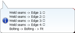
For user-defined insertions you can also use the settings from the DAST tables as predefined values and modify them if desired. If you have changed any settings on the tabs that do not correspond to the preset values of the selected DAST connection, this will be indicated by a  symbol next to the DAST designation. If you move the cursor. When you move the cursor over the symbol, a message will be displayed, e.g.:
To restore the settings to defaults, click the  symbol. To remove the assignment to the DAST presettings, e.g. because you prefer a user-defined connection, click the
  symbol.
The configuration of the front plate connection takes place via the tabs of the dialogue window:
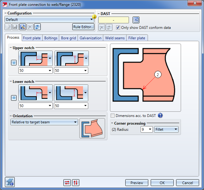
Depending on the fitting situation the beam to be inserted will be notched automatically. The options for the notches can be specified on this tab. Registerkarte fest.
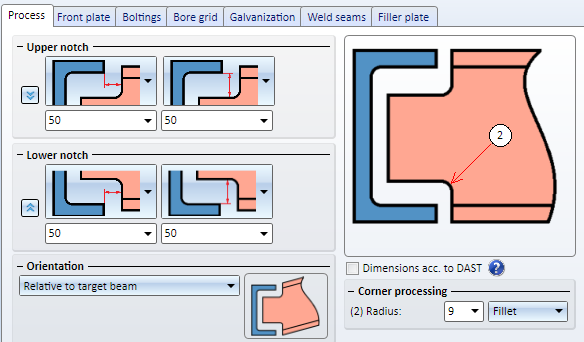
Upper/lower notch
Required are first the distance between the end of the beam to be notched ad the web of the target beam. The horizontal and the vertical distance can be specified separately for the upper notch and the lower notch. Which distance is specified here will be determined via the graphical selection boxes.
| Horizontal distance to | Vertical distance to | ||
|---|---|---|---|
|
|
Web of target beam |
|
Outer edge of notched beam |
|
|
Flange of target beam |
|
Inner flange edge of target beam |
|
|
End of notched beam |
|
Outer flange edge of target beam |
You can apply the settings for the upper notch by clicking on the  icon.
icon.
Orientation
The orientation can be parallel to the web and relative to the target beam or the notched beam.
|
|
Parallel to web / Relative to target beam |
|
|
Parallel to web / Relative to notched beam |
Corner processing
You can choose between the following two options:
If the Dimensions acc. to DAST checkbox is active, the next higher values from the "DSTV Typified Structural Steel Engineering Connections" (Volume 1, "IK Notches" chapter) will be used for the notch length, notch height and the fillet.
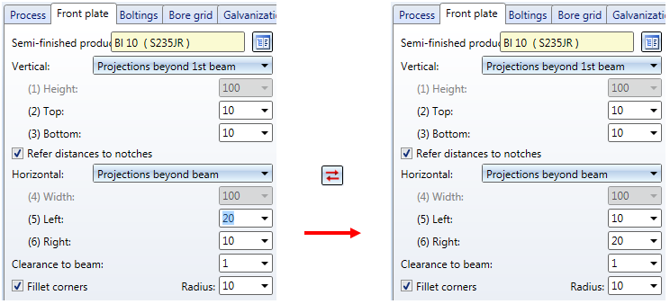
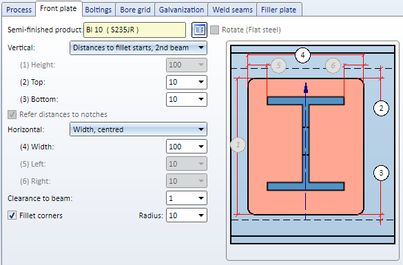
On this tab you specify the type, appearance and size of the plate, and the alignment of the plate in relation to the beam.
|
Semi-finished product |
Click the |
||
|
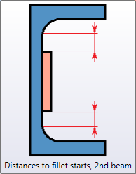
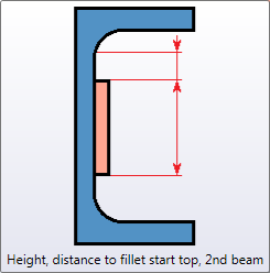
The values beneath Vertical and Horizontal determine the height and width of the plate and its projection. The following, different procedures are available: |
|||
|
Vertical |
|
||
|
Horizontal |
|
||
|
Clearance to beam |
If desired, enter a value for the clearance here, i.e. the distance of the plate to the beam to be connected. |
||
|
Fillet corners |
If you want the corners of the front plate to be filleted, activate this checkbox and enter a fillet radius. |
||
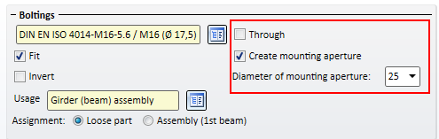
Here you specify the bolting, i.e. the bolt type, diameter etc. Click on the  icon and select the components of the bolting. The default setting is DIN EN ISO 4014-M16-5.6 / M16 (⌀ 17,5). Proceed in the same way as you would do with the Steel Engineering Bolting function.
The bolting will only be inserted if the Fit checkbox is activated.
If you want to Invert the bolting direction, activate the same-named checkbox.
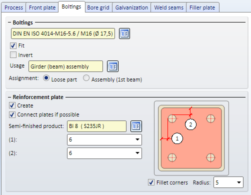
If you want to insert reinforcement plates, activate the Create checkbox. If you want to connect the plates (if possible), activate the Connect plates if possible checkbox. Corners of connected reinforcement plates can also be filleted if desired: Activate the Fillet corners checkbox and enter the fillet radius.
Enter the distance to the bores to the edges of the reinforcement plate, click and choose the type of the plate from the catalogue.
Reinforcement plates - Connected plates (left) and individual plates (right)
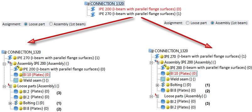
Usage and Assignment
In the Usage field you can specify which usage is to be assigned to the assembly of the 1st beam.
The bolting is inserted as a Bolting group. Next to Assignment you can choose whether this Bolting group and the reinforcement plates are to be assigned to the assembly of the 1st beam or are to be inserted as Loose parts.
If you activate the Assembly (1st beam) option, the Bolting group and the reinforcement plates are assigned to the assembly of the 1st beam.
If you activate the Loose partoption, the Bolting group will be inserted as a separate assembly on the same level as the assembly of the 1st beam. The reinforcement plates will be assigned to a structure assembly called Loose parts that also contains filler plates. This structure assembly is also located on the same level as the 1st beam.
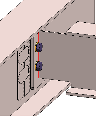
(1) Bolted connection, (2) Reinforcement plate, (3) Filler plate
Please note that the settings for the Usage and the Assignment must be made before the creation of the assembly structure of the connection. After clicking the Preview button, and also after insertion of the connection, a change of these settings will no longer be possible.
Notes on hollow profiles:
If the beam to which the connection is made (2nd beam) is a hollow profile, the Boltings tab will contain additional options:
If both checkboxes are deactivated, the bolt will only run through the first surface of the beam, with no mounting aperture being created in the second surface.
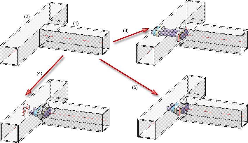
(1) Beam to be connected, (2) Target beam to which the connection is to be made, (3) Through, (4) With mounting aperture, (5) Both checkboxes deactivated
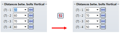
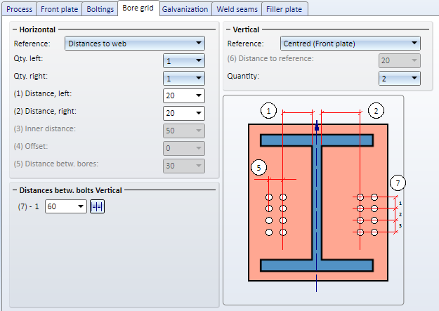
The bore grid determines the pattern of bores for the front plate.
First you need to choose a reference for the Horizontal and Vertical settings. Further value inputs depend on the selected reference.
|
Horizontal, Reference |
Inputs |
|
Distances to plate edge (of front plate) |
|
|
Internal distance
|
|
|
Distances to web |
|
|
Vertical, Reference |
Inputs |
|
Centred |
|
|
Top edge 1st beam |
|
|
Front plate, top |
|
|
Bottom edge 1st beam |
|
|
Front plate, bottom |
|
|
You can use different distances between bores in vertical direction. If all bores are to have the same distance, you can also simplify the value input: Enter the distance value in one of the input fields and click the Equidistant |
|
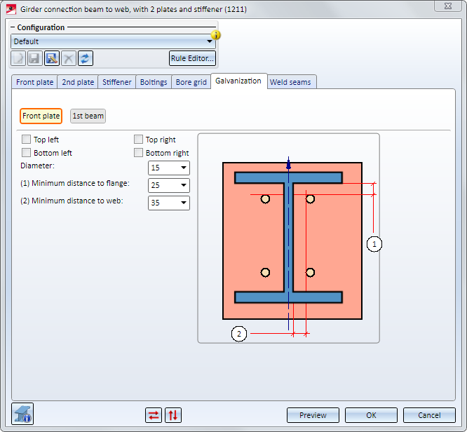
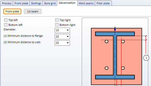
Here you can choose whether you want to apply bores for a zinc plating to the front plate. Activate the corresponding checkboxes and enter the desired diameter. In addition , you can specify a minimum distance of the bores to the flange and to the web.
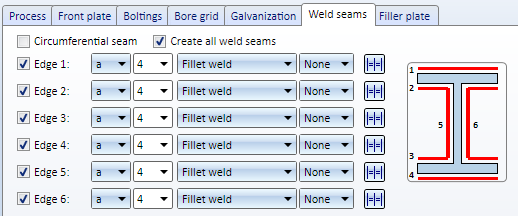
On this tab you can choose, by activating the corresponding checkboxes, which weld seams are to be created:
For each edge you can select the type of the thickness designation, the weld seam thickness the weld seam type and the inspection category. If you want to use the same settings for all edges, click the Equate  symbol.
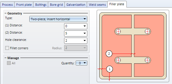
Filler plate
If you want to insert filler plates between the front plate and the 2nd beam, you can specify the number, the type and the size of these plates on the Filler plate tab.
The following geometries for filler plates are available:
Depending on the selected geometry type, enter the required distances and the hole clearance. The hole clearance always refers to the bolting.
(1) Bolt diameter, (2) Two-piece filler plate, (3) Hole clearance
Beneath Manage you can specify the number of filler plates.
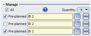
For each filler plate, select the desired plate type in the catalogue . Specify, by activating the corresponding checkboxes, whether the filler plate is to be pre-planned or not. If a filler plate is pre-planned, the 1st beam will be shortened by the thickness of the filler plate. Non-pre-planned filler plates will be created next to the connection.
Activate the All checkbox to set all filler plates to Pre-planned in one step.
Please note that non-pre-planned filler plates will be shown in transparent representation in the drawing, i.e. they will be assigned to Layer 40.
Non-pre-planned filler plate
Filler plates are not assigned to the assembly of the 1st beam, but are placed in a separate structure assembly with the name Loose parts. Also, the usage Filler plate will be assigned to filler plates.
If the bore grid is too narrow, preventing the insertion of the filler plates, the connection will not be created, but the failed operation will be recorded in the feature log:
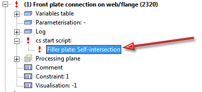
You can then double-click the feature and correct the settings.

Connections + Variants (3-D SE) • Dialogue Window for Connections - Type I (3-D SE) • The Catalogue System for Connections and Variants (3-D-SE)
|
© Copyright 1994-2019, ISD Software und Systeme GmbH |