Project: HiCAD Steel Engineering
Steel Engineering Bolting
Steel Engineering > CAids > SE bolting 
This function bolts plates using a standardized bolting, with
a relevant selection window being displayed.
- Select the standard boltings by activating the relevant radio button.
- Choose the desired
diameter from the corresponding list box.
- Choose the Fitting mode and the type of Production.
- Identify the objects
to be bolted.
- Use the middle mouse
button to end the selection.
The bolting is fitted in the same way as 3-D boltings.
 Please note:
- Boltings can be inserted repeatedly. This means that after insertion of a bolting, the function will not be ended, but remains active. By selecting other parts to be connected, you can then insert the bolting again, with the same settings. What can be changed, though, is the auxiliary grid for the insertion.
- The individual parts of
a steel engineering bolting are combined in an assembly with
the designation (article number) BOLTING.
- In the midpoint of
the bolt pattern, i.e. the assembly BOLTING, an isolated
point is generated. This point can be used to identify a bolting
directly.
- Bore diameters are
generated by default in accordance with the DSTV Test Certificate of 4/11/2002.
- The colour of the axes for boltings can be specified via the Configuration Editor at System settings > Visualisation > 3-D > Take default surface colour from Materials catalogue?.
- Please also note the possibility to perform a mountability check for boltings with the Design Checker
 . It will be checked whether the bolts can be loosened and pulled out without causing collisions, and whether the tool for the tightening of bolts and nuts will have enough space. The mounting will be considered possible if the tool can be moved collision-free when tightening either the bolt or the nut. The Design Checker can be found in the 3-D, Further function group of the Information tab.
- When inserting bolts in an auto-generated assembly in Steel or Metal Engineering, the dimensions of the assembly will be determined by the production type specified in the settings for bolts. If Site assembly has been selected, the part dimensions will not be changed by the insertion of the standard part, i.e. the dimensions will then correspond to the shipping dimensions.
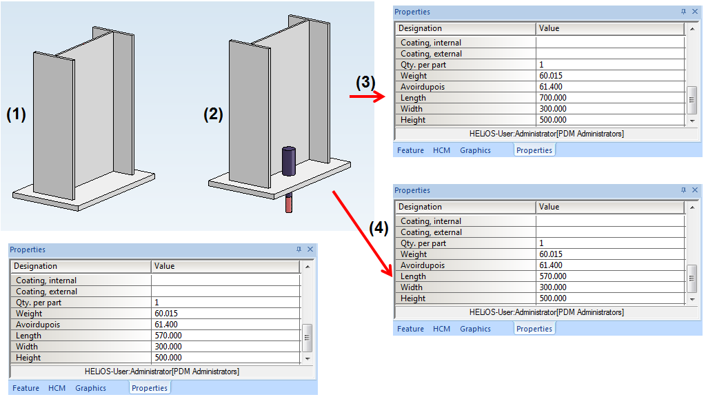
(1) Steel Engineering assembly with original dimensions, (2) Insertion of an anchor bolt,
(3) Dimensions of assembly after insertion of bolt with production type "Factory assembly",
(4) Dimensions of assembly after insertion of bolt with production type "Site assembly"


Further Connections + Construction Aids (3-D SE) • Steel Engineering
Functions • General
Information (3-D SE) • Standard
Parts and Boltings (3-D)
|
© Copyright 1994-2019, ISD Software und Systeme GmbH
Version 2402 - HiCAD Steel Engineering
Date: 04/11/2019
|
> Feedback on this topic
|