Project: HiCAD Profile Installation
Profile Installation > New/Change > Profile installation
On the Global settings you specify the most important basic settings for an installation layer:
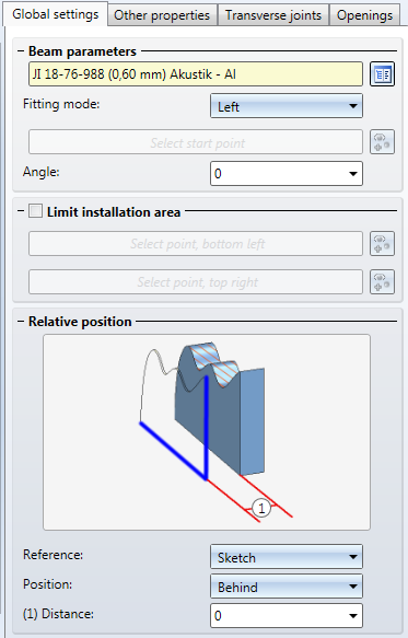
The following setting options are available here:
| Select beam/profile from catalogue |
Here you select the profile that is to represent the layer from a catalogue.
|
| Fitting mode |
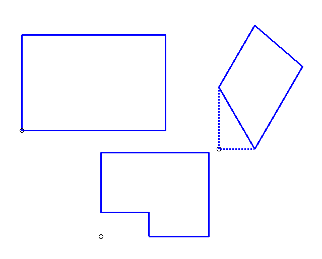
The fitting mode determines in which direction the profile is to be installed. If you choose Left, the start point will be placed in the lower left corner of the sketch area. In a rectangular sketch in exact X- and Y-direction, this point coincides with the lower left corner; if the sketch has a different shape, it can also lie outside the sketch.
Examples with a start point on the left for various sketches The option Right behaves in the same way. Alternatively, you can use the Select start point mode and select a start point of your choice. For this purpose (if the Select start point fitting mode is used), the same-named field will be activated. You can then choose any point in your model drawing on the sketch plane as a start point.
|
| Angle |
The profile will be rotated according to the angle entered here. Select, for instance, an angle of 45° to insert the profile diagonally. In the process, the entire processing plane will be rotated according to this angle; for instance, a start point at the bottom left will be moved to the top left if you choose an Angle of 90°. If you define your own start point via the Select start point mode, this start point, will, of course, not be rotated, but remains where it was.
|
| Limit installation area |
By default, the entire sketch area will be covered with profiles. But you have also the option to limit the installation area per level. To do this, activate the Limit installation area check. HiCAD will then prompt you to identify 2 points; first, the bottom left point; then top right point, seen from the processing plane to the sketch. Profiles will then only be installed within the rectangle defined by these 2 points.
|
| Relative position | |
|
Reference:, Position: |
If you want to place profiles on several layers, these must in most cases be installed on different "heights", i.e. different distances to the sketch plane. To determine these distances, Reference layers are used. A surface will always be placed in relation to a reference layer. For Position you can choose between In front and behind; as Reference layers you can choose the sketch plane and all other layers of this profile installation. "In front" and "Behind" refer to the view onto the installation coordinate system: Layers in front (positive Z-axis) will cover layers behind (negative Z-axis). If a layer lies in front of another layer, this means that its read side is on the same height as the front side of the layer behind. The Example: Insulating Layer demonstrates by way of a facade with an insulating layer how two layers can placed on top of one another. If you later delete a layer referenced in this way, a security prompt will be displayed: Really delete layer 'Layer name'?. If you choose Yes, the layer will be deleted, and for the layers that had referred to the deleted layer, the Reference layer will be set to Sketch and the Distance will be set in such a way that this plane will retain its position.
|
| Distance |
Here you can define a distance of the layer to the Reference layer. For instance, you can enter a distance of 10 here to create a clearance. |


|
© Copyright 1994-2019, ISD Software und Systeme GmbH |