
Project: HiCAD Profile Installation
Profile Installation > New/Change > Profile installation
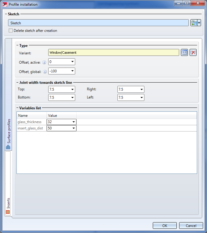
Via the Openings tab you can automatically place Inserts. You can find the relevant functionality on the same-named side tab of the Profile Installation dialogue window.
It is used in a similar way as the Element Installation function.
While the Inserts tab is active, all openings in the sketch which can be filled with inserts will be highlighted in the model drawing. Selected openings will be highlighted in red, non-selected openings in blue.
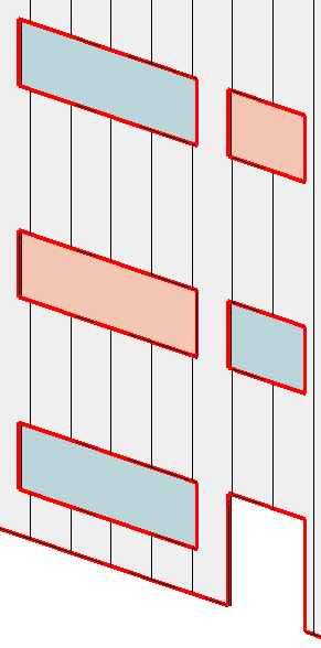
View in the model drawing. 2 openings have been selected.
When you open the tab, all openings in the model drawing will be selected initially. Clicking on a particular opening deselects all the other openings. Clicking on a particular opening while holding down the CTRL key deselects (or selects) only this opening. Also, you can draw a selection rectangle while holding down the CTRL key and the left mouse button to add all openings within this rectangle to your selection.
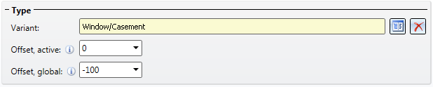
In the dialogue window you can now choose a variant that is to be placed into the selected opening(s). Furthermore, you can define 2 offsets here: Offset, active concerns only the currently selected elements and may differ per element; in contrast, Offset, global applies to all inserts in the profile installation drawing, i.e. it will be identical for all elements. Positive values cause displacements in the direction above the sketch plane, negative values in the direction below the sketch plane, accordingly.
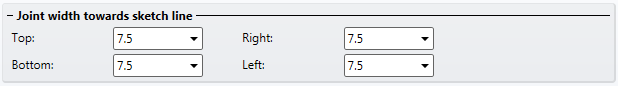
For all 4 directions you can specify assign a Joint width towards sketch line if you do not want the inserts to border directly on the sketch line. This setting concerns the currently selected openings.
![]() Please note:
Please note:
If you want to configure the distance of the profiles to the sketch line, you can do this on the Openings tab of the Surface profiles side tab.
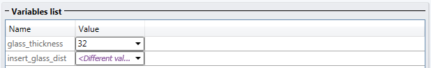
In the lower area of the dialogue, further variables or settings can be defined for the selected variant. For the available variant Window/Casing, these are variable for the glass thickness and the distance of the glass pane to the frame.
![]() Please note:
Please note:
For all settings that are set individually per opening, the following rule applies: If multiple openings have been selected which, however, differ with regard to one value, the message <Different values> instead of a value will be displayed in the relevant input field . If you leave this setting unchanged, the openings will preserve their individual values. If you enter a value here, this value will subsequently be applied to all selected openings.

You have the option to create your own variants to use them as inserts. Proceed exactly as you would do with Customer-specific Installation Elements, with the difference that inserts need to be saved to the catalogue Factory standards > Installation planning - Parts+Processings > Profile installation > Inserts.
If you have already created customer-specific inserts for utilization in the Element Installation module, you can also use them in the Profile Installation module, by simply creating a new catalogue entry in the above path. This can also refer to the same .KRA file, so that these do not need to exist twice.
![]() Important:
Important:
Variants for utilization as inserts must use the mandatory spelling for variables used from HiCAD 2019 SP1 onwards (i_l, i_h usw.)! Variants based on the old spelling (width and length), cannot be used for this!

|
© Copyright 1994-2019, ISD Software und Systeme GmbH |